


Appendix – Re-Assembly Procedure
1
22
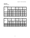
The connections are as follows:
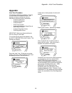
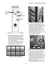
Figure 2 : Motor Side Module Position
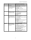
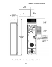
3. Make the following electrical connections
from the DC Bus Board in the Line Side
Converter enclosure flowing straight
across to the PWM DC Bus Board in the
Motor Side Inverter enclosure. See Figure
for more information.
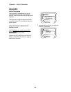
Use a 10mm hex socket with extension to
connect a M6 nut, lock washer, and flat
washer torqued to 7.9 N-m (70 in-lbs).
Wire
Number
From DC
Bus
Board
To PWM
DC Bus
Board
Reference
Name
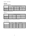
80 A17-E16 A18-E22 +Bus
80A A17-E15 A18-E21 +Bus
81 A17-E18 A18-E24 -Bus
81A A17-E17 A18-E23 -Bus
82 A17-E13 A18-E19 Neutral
Table 1 : DC Bus Connections 7
2
3
3
Motor
Contactor
Contactor
Control Bd (A9)
Motor Field
Controller
(A24)
Motor Side
Inverter
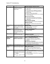
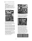
Figure 2 : DC Bus Connections
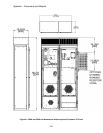
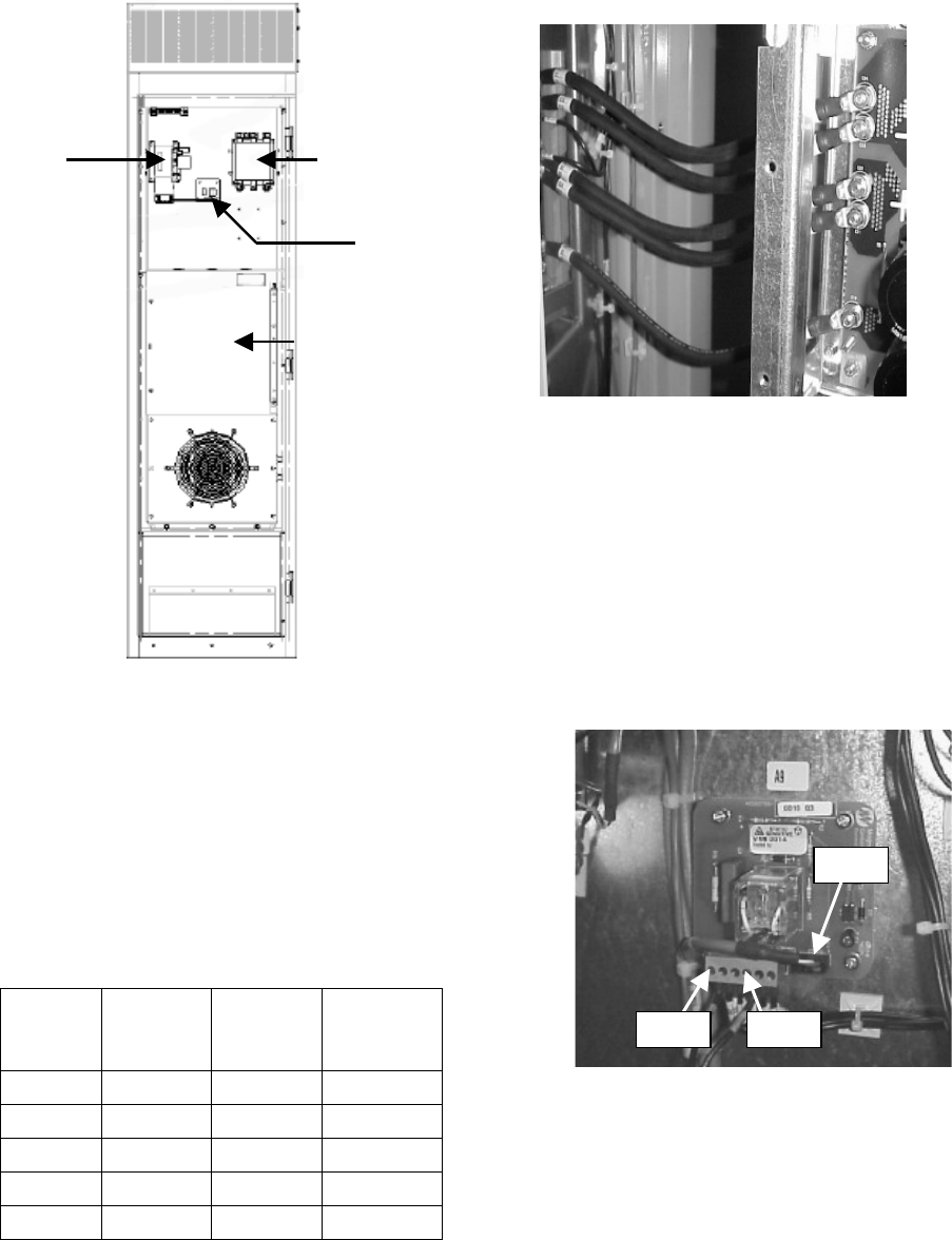
4. Next, connect the wire harness JCC1
coiled up on the right side of the Line Side
Converter to the Contactor Control Board
(A9). Dress and secure all cables.
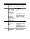
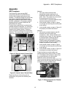
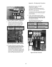
Connect wire A9/TB1/1 to A9-TB1 pin 1
and A9/TB1/4 to A9-TB1 pin 4 of the
Contactor Control Board (A9) in the Motor
Side Inverter. Use a 1/8” x 4” flat
screwdriver for the TB1 terminals. Torque
to 0.23-0.28 N-m (2-2.5 in-lbs).
See Figure 2 for reference.
JCC1
TB1-4
TB1-1
Figure 2 : Contactor Control Board (A9)
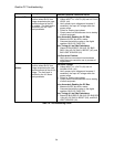
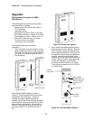
5. Next, connect the wire harness A24J1
coiled up on the right side of the Line Side
Converter to J1 on the Field Control
Module (A24) and A24J3 coiled up on the
right side of the Line Side Converter to J3
on the Field Control Module (A24). J1 and
J3 are located on the bottom right hand
corner of the Field Supply Board. Dress
and secure all cables.
Connect appropriately sized wires for the
intended motor field current directly to the
99