


Appendix – Re-Assembly Procedure
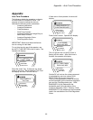
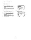
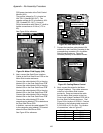
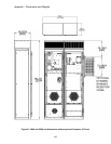
The positive voltage for F1 is located on
A24-TB1-2 (labeled SW OUT). The
negative voltage for F2 is located on A24-
TB1-3 (labeled DC- OUT). Use a #2
Phillips screwdriver with 50mm (2”) shaft to
tighten connections to 2.0 N-m (17.5 in-
lbs).
4
4
5
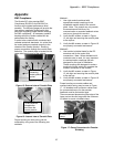
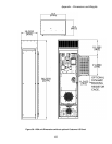
Figure 25: Dual Gate Drive PCB
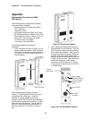
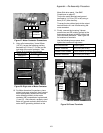
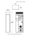
7. Connect the interface cable labeled J5A
coiled-up on the Line Side Converter to the
corresponding connector J5 in the Motor
Side Inverter enclosure. Figure 26
indicates proximity to the cabinet blower.
6
PCB power terminals at the Field Control
Module (A24).
See Figure 2 for reference.
Figure 2 : Motor Field Supply (A24)
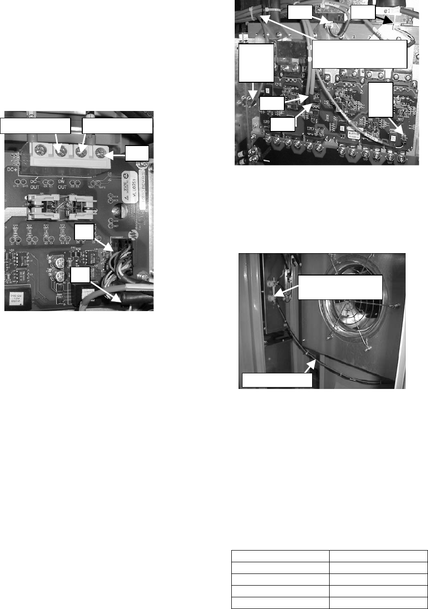
6. Next, connect the Gate Driver Interface
Cables to the Dual Gate Driver PCB on the
Motor Side Inverter enclosure.
Connect the cable labeled JG1 to the plug
labeled JG1 on the Dual Gate Driver PCB.
Connect the cable labeled JG2 to the plug
labeled JG2 on the Dual Gate Driver PCB.
Connect the cable labeled JG3 to the plug
labeled JG3 on the Dual Gate Driver PCB.
Connect the cable labeled JG4 to the plug
labeled JG4 on the Dual Gate Driver PCB.
Connect the cable labeled CT5 to the
respective plug labeled CT5 located above
the Dual Gate Driver PCB.
In Addition, connect the cable labeled CT6
to the respective plug labeled CT6 located
above the Dual Gate Driver PCB.
See Figure 2 for reference.
CT5 CT6
JG2
JG1
JG4
power
supply
JG3
DC
bus
Cable assembly is in
converter cabinet
DC- OUT (F2-) SW OUT (F1+)
TB1
J1
J3
Plug inverter
cabinet fan in here
Fan cable J5
A
Figure 2 : Cooling Blower Control
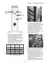
8. Next, connect the wires for the Motor
Voltage Feedback. The cables wires are
coiled-up in the Motor Side Inverter
enclosure. Dress and secure the cable
from the Motor Side Inverter to the Line
Control and Voltage Feedback PCB (A8) in
the Line Side Converter enclosure. See
Figure 20 for location of PCB A8. Connect
the wires by the following table torqued to
0.23-0.28 N-m (2-2.5 in-lbs). For location
of connections, refer to Figure 27.
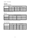
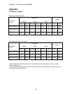
Wire Number A8 connections
19 TB2-1
16 TB2-2
25 TB2-3
26 TB2-4
100