


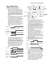
Quattro DC Interconnections
Contact
Cfirm
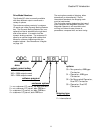
Encoder Connections
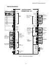
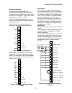
The Quattro DC has connections for an
incremental two-channel quadrature encoder.
The Quattro DC requires the use of an encoder
coupled to the motor shaft. The encoder power
can be either a +5VDC or +12VDC.
The encoder pulses per revolution must be
entered in the ENCODER PULSES parameter
in the A1 submenu.
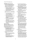
Figure 3 shows the encoder connection
terminals for non-single ended applications.
17
Figure 3: Encoder Connections
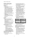
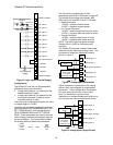
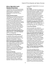
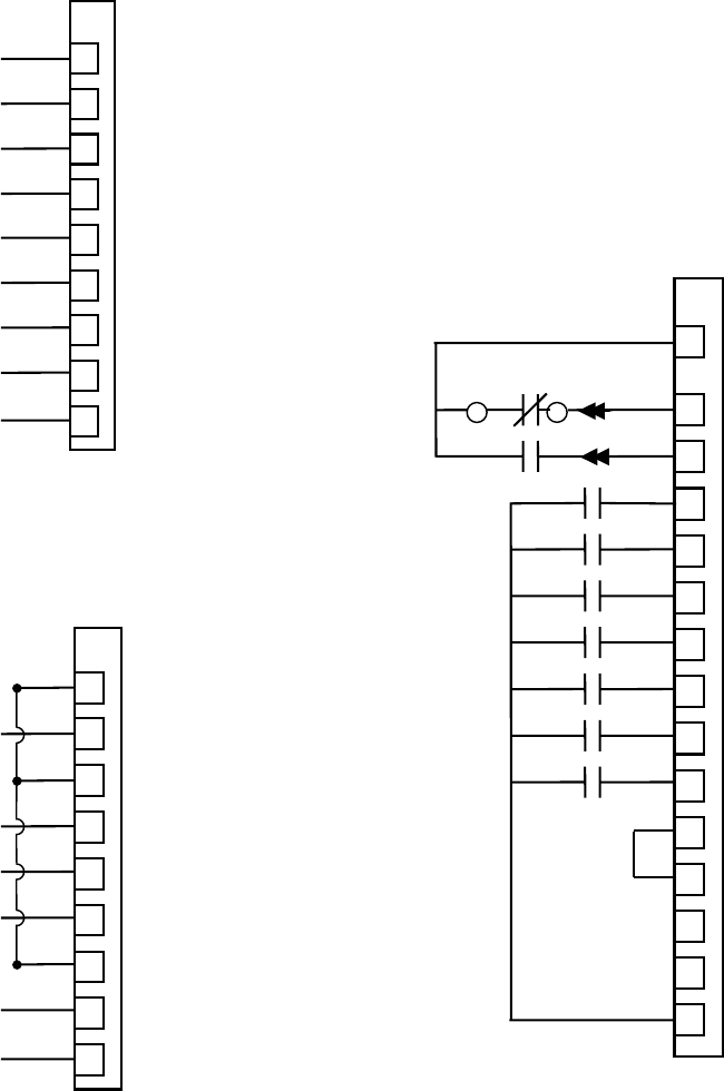
Below shows the connection for the encoder
option card, if they are configured to be single
ended. This configuration is not recommended,
since, the Quattro DC encoder noise immunity
circuitry is not in effect.
Figure 4: Encoder Connections (Single-
Ended)
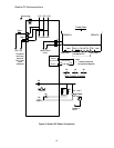
Logic Inputs
The Quattro DC’s nine programmable logic
inputs are opto-isolated.
For more information
on programming logic inputs, see Logic Inputs
C2 submenu on page 61.
The inputs become
“true” by closing contacts or switches between
the logic input terminal and voltage source
common (or voltage source). The inputs are
sourcing inputs – nominally sitting at common
and when the contacts or switches are closed,
turning “true” at 24VDC. The voltage supply for
the logic inputs is 24VDC.
IMPORTANT
/A
A
TB1
34
35
36
37
38
39
40
41
42
/B
B
/Z
Z
C_ISO
+5V_ISO
+12V_ISO
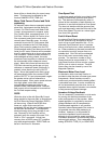
Internal 24VDC power supply has a capacity of
100 mA
Note: Logic input 1 and 2 are reserved and pre-
wired for CONTACT CFIRM and CTR PWR
SENSE respectively.
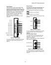
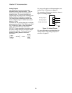
The choices for the voltage source common (or
voltage source) depend on if the user is using
an external voltage supply or using the internal
voltage supply. See Figure 5 for internal supply
example and Figure 6 for external supply
example.
A
9JCC1-2
A
9JCC1-1
A
9TB1
11
logic input 1
logic input 2
TB1
Figure 5: Logic Input Diagram (Internal
Supply)
1
2
+24VDC isolated
6
5
10
43
46
44
logic input common
+24VDC iso. common
+24VDC isolated
+24VDC iso. common
3
4
5
6
7
8
9
logic input 3
logic input 4
logic input 5
logic input 6
logic input 7
logic input 8
logic input 9
45
+24VDC iso. common
CTR PWR Sense
/A
A
TB1
34
35
36
37
38
39
40
41
42
/B
B
/Z
Z
C_ISO
+5V_ISO
+12V_ISO