


Quattro DC Parameters
Parameters
Parameter Introduction
This section describes the parameter menu
structure of the Magnetek Operator, how to
navigate this menu structure, and a detailed
description of each parameter.
Parameters are grouped under six major
menus:
• ADJUST A0
• CONFIGURE C0
• UTILITY U0
• FAULTS F0
• DISPLAY 1 D0
• DISPLAY 2 D0
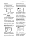
When the SUB-MENU LED is off, the currently
selected menu is shown on the top line of the
Digital Operator display and the currently
selected sub-menu is shown on the bottom line
of the Digital Operator display.
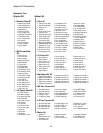
Menus
Each menu has a number of sub-menus.
Following is a listing of the menus:
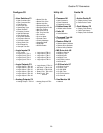
• ADJUST A0
• CONFIGURE C0
• UTILITY U0
• FAULTS F0
• DISPLAY 1 D0
• DISPLAY 2 D0
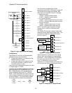
Display 1 D0
Adjust A0 Configure C0 Utility U0 Faults F0 Display 2 D0
→ Active
Faults F1
→ Fault
History F2
→ Elevator
Data D1
→ MS Power
Data D2
→ LS Power
Data D3
→ Elevator
Data D1
→ MS Power
Data D2
→ LS Power
Data D3
→ User
Switches C1
→ Logic Inputs
C2
→ Logic
Outputs C3
→ Analog
Outputs C4
→ Drive A1
→ S-Curves A2
→ MultiStep Ref
A3
→ Motor side
Power
Convert A4
→ Line side
Power
Convert A5
→ Motor
Params A6
→ Password
U1
→ Hidden
Items U2
→ Units U3
→ Ovrspeed
Test U4
→ Restore
Dflts U5
→ MS Drive
Info U6
→ LS Drive
Info U7
→ Hex Monitor
U8
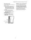
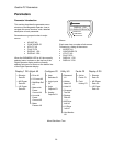
RUN/FAULT
SUB MENU
DATA ENT
DISPLAY 1 D0
D1 ELEVATOR DAT
A
Menu/Sub-Menu Tree
26