


Quattro DC Startup Guide
− Open F1 and F2 and ensure control power
brought into fuse F1 and F2 is 230VAC!
IMPORTANT: Double-check all the power
wires and motor wires to make sure that they
are securely tightened down to their respective
lugs (loose wire connections may cause
problems at any time).
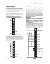
Grounding considerations
1. Encoder
a. Encoder isolation
− The encoder must be electrically
isolated from the motor frame and
the motor shaft.
b. Encoder cable
− The cable type should PVC braided
shielded type with three 22ga
twisted pairs. A and A/, B and B/,
common and V should be the
signals paired together.
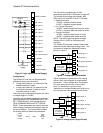
− The encoder shield is not to be
connected at the encoder end. On
the drive side of the cable a portion
of PVC material 1inch [25mm]
should be removed approximately
12inches [300mm] from the
connection to the customer
interface PCB (A6) to expose the
shield material. This point is
required to be secured under a
clamp located under the control
tray. Do not connect the shield to
any other point. Refer to the EMC
Compliance on page 97.
2. Motor frame
a. The motor frame is required to be
grounded. The bond wire should be
returned to the common ground point
located in the Quattro enclosure (PE).
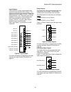
3. Three phase power
a. The three phase wires must be run
with a ground wire. This ground wire,
which is connected back to the utility
ground, is required to be connected to
the Quattro ground (PE).
4. Control power, 230VAC
a. The neutral side of the control power is
required to be grounded at the Quattro
ground (PE).
Initial adjustments after power up
Encoder Set-up
Electrical interference and mechanical speed
modulations are common problems that can
result in improper speed feedback getting to
the drive. To help avoid these common
problems, the following electrical and
mechanical considerations are suggested.
IMPORTANT
Proper encoder speed feedback is essential
for a drive to provide proper motor control.
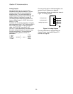
Electrical Requirements:
− Insulate both the encoder case and shaft
from the motor
− Incremental encoder type
− Use twisted pair cable with shield tied to
chassis ground at drive end
− Use limited slew rate differential line
drivers
− Do not allow capacitors from internal
encoder electronics to case
− Do not exceed the operating specification
of the encoder/drive (300Khz @ rated
motor speed maximum)
− Use the proper encoder supply voltage
and use the highest possible voltage
available. The Quattro DC provides both
5VDC and 12VDC. Magnetek
recommends using the 12VDC for the
encoder supply.
Mechanical Considerations:
− Use direct motor mounting without
couplings
− Use hub or hollow shaft encoder with
concentric motor stub shaft
− If possible, use a mechanical protective
cover for exposed encoders
− It is not advisable to use friction wheels
Enter / Verify the encoder pulses entered in
the ENCODER PULSES (A1) parameter
matches the encoder’s nameplate.
Motor Parameter Set-up
Enter / Verify the following from the motor’s
nameplate:
1. Motor Current (RATED MTR CURRENT
(A6))
2. Motor Voltage (RATED ARM VOLTS (A6))
3. Motor field amps, forcing (FULL FLD
AMPS (A6))
4. Motor field amps, running (WEAK FLD
AMPS (A6))
5. Motor field amps, standing (STNDBY
FIELD (A6))
Hoist way Parameter Set-up
Enter / Verify the hoist way parameters:
1. CONTRACT CAR SPD (A1) parameter
programs the elevator contract speed in
ft/min or m/s.
13