Chapter 8: Magnum Router Specialized Functions
___________________________________________________________________
8-2
For Example:
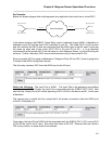
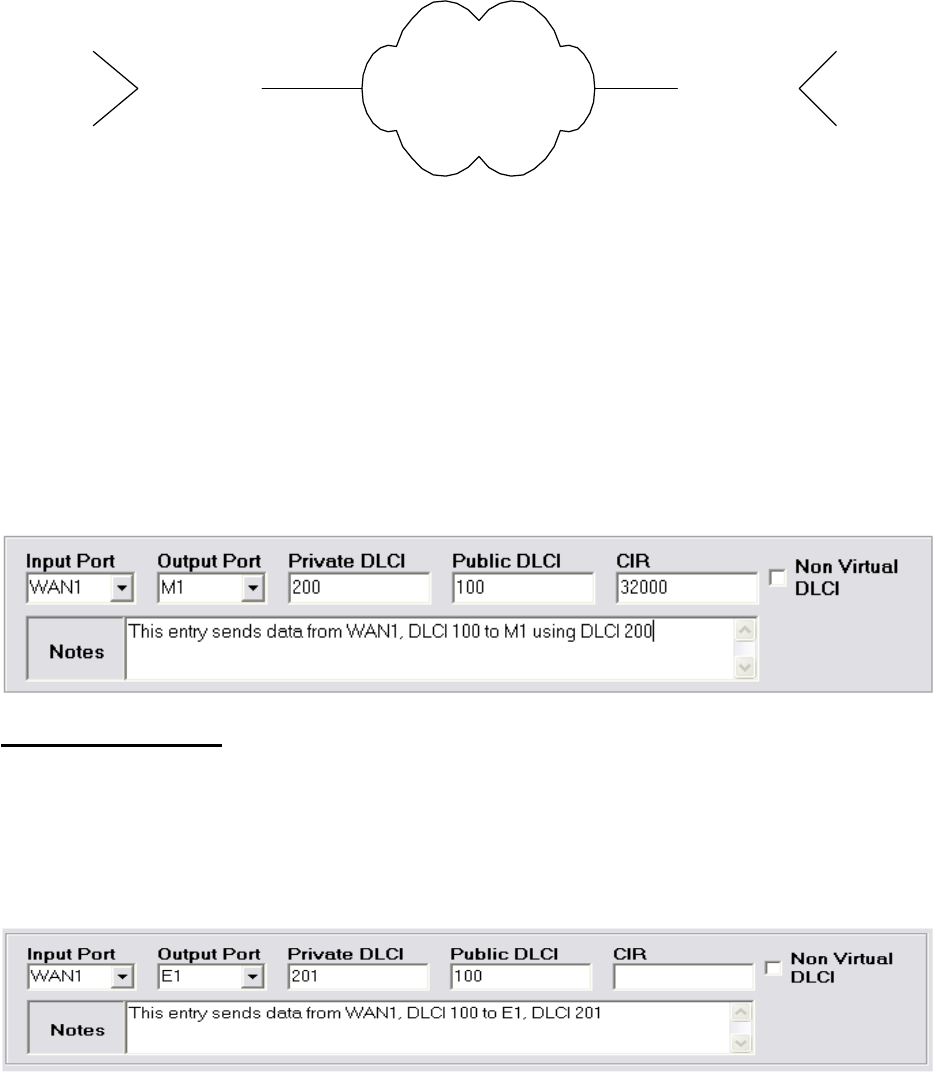
Below is a simple diagram that could represent one application that would use a virtual DLCI.
Public Frame Relay
Magnum R outer M1 Magnum Rout er M1
Magnum Rout er E1
Magnum R outer E1
Magnum Rout er WAN1
DLCI 100
DLCI 100
Magnum R outer WAN1
DLCI 200
DLCI 201
DLCI 200
DLCI 201
In the above drawing, the PUBLIC Frame Relay circuit is attached to port WAN1, a Marathon is
attached to port M1 and the local LAN is attached to port E1. The Public DLCI is 100 on each
end, but note that the DLCI’s that are connected from the WAN1 port to the M1 and E1 ports are
the same on each end of the circuit (DLCI 200 to M1 and 201 to E1). It is an absolute
requirement that the private DLCI’s be the same on each Magnum Router, or Virtual Routing will
not work. Further, the public DLCI cannot be the same as any of the private DLCI’s.
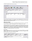
Since one public DLCI is being multiplexed to 2 Magnum Ports (M1 and E1), there is going to be
2 entries in the WAN Configuration screen.
The first entry creates a PVC from the WAN1 port to the M1 port.
Notice the following:
The Input Port is WAN1. The Input Port is the gathering and splitting
point of a virtual DLCI. Further, the Input Port is associated with the PUBLIC DLCI (100). Also
note that the Output Port of M1 will be reporting a DLCI of 200 to the device on M1, in this case
a Marathon.
The second entry is similar the first, except that it will create a connection from the WAN1 port
to the E1 (Ethernet) port.
Once again, the Input Port of WAN1 will be associated with the PUBLIC DLCI (100), and a DLCI
of 201 will be sent to the E1 port. But notice that there is NO CIR. Ethernet does not utilize a
CIR for any reason, so none needs to be entered.


