Maxtor Atlas 10K V 5-51
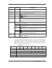
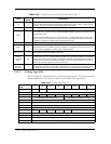
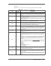
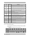
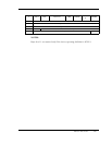
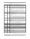
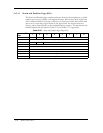
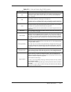
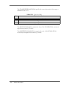
Table 5-71 Notch and Partition Page-Field Descriptions
Data Field Description
PS
Parameters Savable. This bit is only used with the MODE SENSE command. The
returned value of 0 indicates that the target is not capable of saving this page in a
non-volatile vendor specific location. This bit is reserved with the MODE SE-
LECT command.
ND
Notched (banded) Drive. A value of 0 indicates that the drive is not notched and
that all other parameters in this page are returned as 0.
The default value of 1 indicates that the device is notched. For each supported ac-
tive notch value, this page defines the starting and ending boundaries of the notch.
LPN
Logical or Physical Notch. The default value of 0 indicates that the boundaries of
the notch are based on the physical parameters of the logical unit. The cylinder is
considered most significant and the head least significant.
A value of 1 indicates that the notch boundaries are based on logical blocks of the
logical unit.
MaxNotch
This field indicates the maximum number of notches supported by the logical unit.
The value cannot be changed.
Active Notch
The Active Notch field indicates the notch referenced by this, and subsequent
MODE SELECT and MODE SENSE commands. The value in this field can be
changed by a later MODE SELECT command. The value of the active notch must
be = 0 and = 24. An active notch of 0 indicates that this and subsequent MODE
SELECT and MODE SENSE commands refer to the parameters that apply across
all notches.
Starting Boundary
This field indicates the beginning of the active notch or, if the active notch is 0, the
beginning boundary of the logical unit. If the LPN value is 1, the starting boundary
is a Logical Block Address.
If the LPN value is 0, the three most significant bytes designate the starting cylin-
der number and the least significant byte is the starting head number. This field is
unchangeable. When used with the MODE SELECT command, this field is ig-
nored.
Ending Boundary
This field indicates the ending of the active notch, or if the active notch is zero, the
ending of the logical unit. If the LPN value is 0, the 3 most significant bytes des-
ignate the ending cylinder and the least significant byte is the ending head number.
Pages Notched
This is a 64-bit bitmap that indicates which MODE command pages contain pa-
rameters that may be different for different notches. The most significant bit
(MSB) corresponds to Page 3Fh (Vendor-Unique Caching Page), and the least sig-
nificant bit (LSB) corresponds to Page 00h
(Unit Attention Control Page).
If a bit is 1, the corresponding mode page contains parameters that may be differ-
ent for different notches.
If a bit is 0, the corresponding mode page contains parameters that are constant for
all notches.
The value of 1 in bits 3 and 12 indicates that Page 03h and 0Ch contain different
parameters for different notches.


