


3-22 Maxtor Atlas 10K V
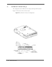
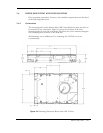
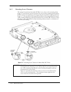
3.6.2 Mounting Screw Clearance
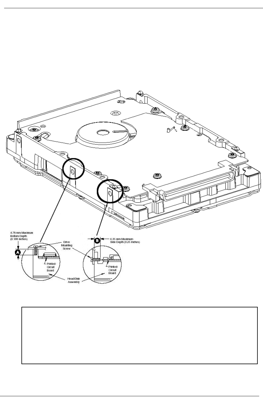
The printed-circuit board assembly (PCBA) is very close to the mounting holes.
Figure 3-7 specifies the clearance between the screws in the mounting holes and the
PCBA. Do not use mounting screws longer than the maximum lengths specified in
Figure 3-7. The specified screw length allows full use of the mounting-hole threads,
while avoiding damaging or placing unwanted stress on the PCBA. Clearance from
the drive to any other surface (except mounting surfaces) must be a minimum of
1.25 mm (0.05 inches).
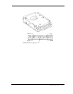
Figure 3-7 Mounting Screw Clearance for Maxtor Atlas 10K V Drive
CAUTION: The PCB is very close to the mounting holes. Do not exceed the speci-
fied length for the mounting screws. The specified screw length allows full
use of the mounting-hole threads, while avoiding damaging or placing
unwanted stress on the PCB.
Figure 3-7 specifies the minimum clearance between the PCB and the
screws in the mounting holes. The maximum torque applied to the
screws must not exceed 8.6 inch-pounds.