


10 - 2 10 - 2
MELSEC-Q
10 MAINTENANCE AND INSPECTION
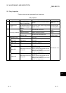
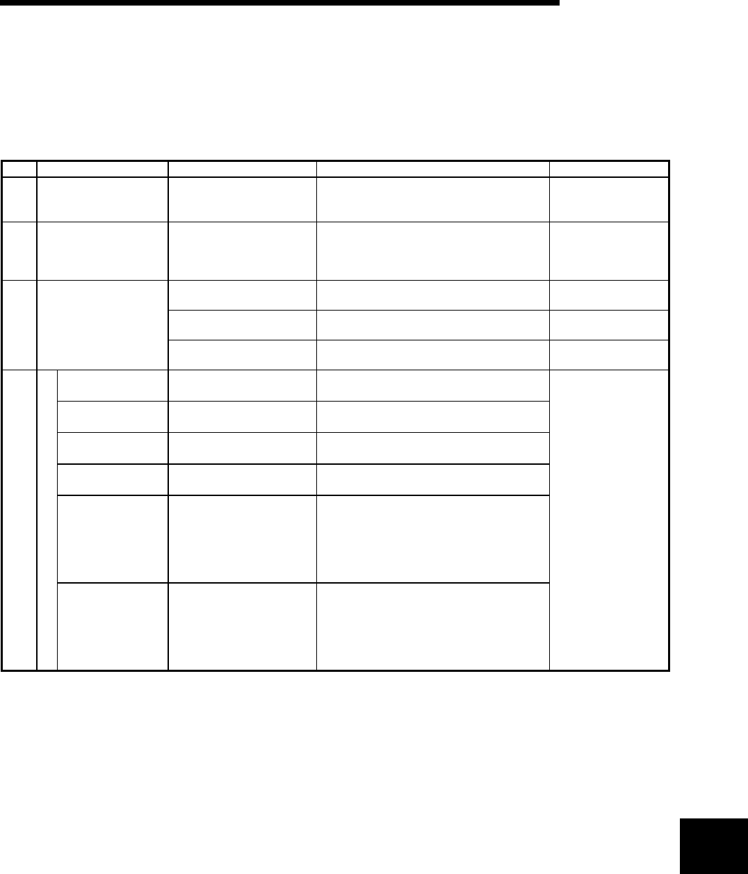
10.1 Daily Inspection
The items that must be inspected daily are listed below.
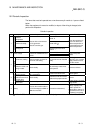
Daily inspection
Item Inspection Item Inspection Judgment Criteria Remedy
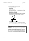
1 Installation of base unit
Check that fixing screws
are not loose and the
cover is not dislocated.
The screws and cover must be installed
securely.
Further tighten the
screws.
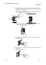
2
Installation of I/O
module
Check that the module is
not dislocated and the unit
fixing hook is engaged
securely.
The unit fixing hook must be engaged and
installed securely.
Securely engaged
the unit fixing hook.
Check for loose terminal
screws.
Screws should not be loose.
Retighten terminal
screws
Check distance between
Solderless terminals.
The proper clearance should be provided
between Solderless terminals
Correct.
3 Connecting conditions
Check connectors of
extension cable.
Connections should no be loose.
Retighten connector
mounting screws.
Power supply
"
POWER
"
LED
Check that the LED is ON.
The LED must be ON. (Abnormal if the
LED is OFF.)
CPU
"
RUN
"
LED
Check that the LED is ON
in RUN status.
The LED must be ON. (Abnormal if the
LED is OFF.)
CPU
"
ERR.
"
LED
Check that the LED is
OFF.
The LED must be OFF. (Abnormal if the
LED is ON or flickering.)
CPU
"
BAT.
"
LED
Check that the LED is
OFF.
The LED must be OFF. (Abnormal if the
LED is ON.)
Input LED
Check that the LED turns
ON and OFF.
The LED must be ON when the input
power is turned ON.
The LED must be extinguished when the
input power is turned OFF.
(Abnormal if the LED does not turn ON or
turn OFF as indicated above.)
4
Module indication LED
Output LED
Check that the LED turns
ON and OFF.
The LED turns ON when the output power
is turned ON.
The LED must be extinguished when the
output power is turned OFF.
(Abnormal if the LED does not turn ON or
turn OFF as indicated above.)
Follow Section 10.2.
10