


8 - 7 8 - 7
MELSEC-Q
8 EMC AND LOW VOLTAGE DIRECTIVE
(c) CC-Link module
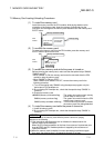
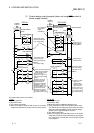
1) Be sure to ground the cable shield that is connected to the CC-Link
module close to the exit of control panel or to any of the CC-Link stations
within 30 cm (11.81 inch) from the module or stations.
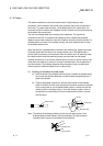
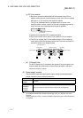
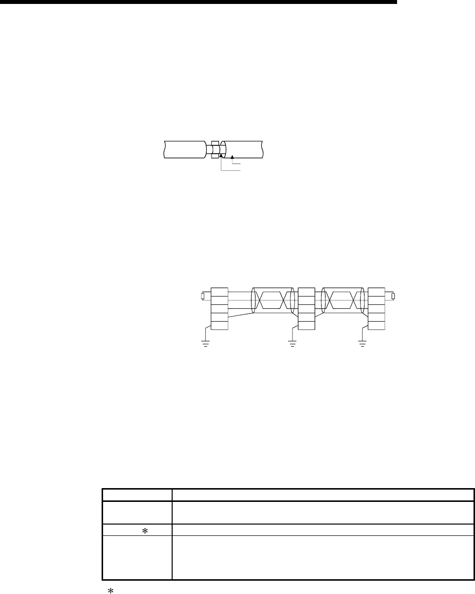
The CC-Link dedicated cable is a shielded cable. As shown in the
illustration below, remove a portion of the outer covering and ground as
large a surface area of the exposed shield part as possible.
CC-Link dedicated cable
Shield
2) Always use the specified CC-Link dedicated cable.
3) Do not use a ferrite core for the CC-Link module or CC-Link stations.
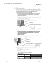
4) The CC-Link module, the CC-Link stations and the FG line inside the
control panel should be connected at both the FG terminal and the SLD
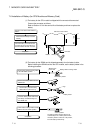
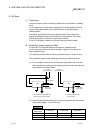
terminal as shown in the diagram below.
[Simplified diagram]
T
erminal resistor
Master station
Remote I/O station
Local station
Terminal resisto
r
CC-Link
dedicated
cable
CC-Link
dedicated
cable
DA
DB
DG
SLD
FG
DA
DB
DG
SLD
FG
DA
DB
DG
SLD
FG
(Blue)
(White)
(Yellow)
(d) I/O signal lines
For the I/O signal lines, if extracted to the outside of the control panel, also
ensure to earth the shield section of these lines and cables in the same
manner as in item (1) above.
(2) Power supply module
The precautions required for each power supply module are described below.
Always observe the items noted as precautions.
Model Precautions
A1S61P
A1S62P
Not usable
A1S63P ( 1) Use the CE marked 24VDC panel power equipment.
A1S61PEU
A1S62PEU
A1S61PN
A1S62PN
Always ground the LG and FG terminals after short-circuiting them.
( 1) If sufficient filter circuitry is built into the 24VDC external power supply module, the noise
generated by A1S63P will be absorbed by that filter circuit, so a line filter may not be
required.
Filtering circuitry of version F or later of A1S63P is improved so that a external line filter is
not required.