


4 - 9 4 - 9
MELSEC-Q
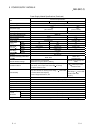
4 HARDWARE SPECIFICATION OF THE CPU MODULE
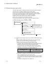
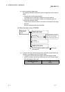
(b) Operations with CPU module (automatic write to standard ROM)
1) Switch OFF the power supply to the PLC.
2) Mount the memory card that contains the parameters and programs to
be booted onto the CPU module.
3) Set the parameter's valid drive in the mounted memory card with the
CPU module's dip switches.
• When a SRAM card is mounted: SW2 : ON, SW3 : OFF
• When a Flash card/ATA card is mounted: SW2 : OFF, SW3 : ON
4) Switch on the power supply to the PLC.
5) "BOOT" LED will flicker when automatic write to standard ROM has
been completed, and the CPU module will assume a suspension error
status.
6) Switch OFF the power supply to the PLC.
7) Remove the memory card, and then set the parameter's valid drive in
the standard ROM with the CPU module's dip switches.
• Standard ROM: SW2 : ON, SW3 : ON
(c) The parameters and programs will be booted from the standard ROM to the
program memory when the PLC is switched on to enable actual operations.