


11 - 71 11 - 71
MELSEC-Q
11 TROUBLESHOOTING
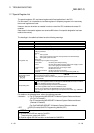
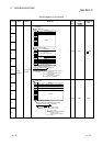
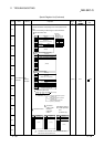
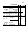
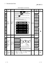
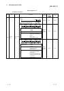
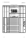
Special Register List
(2) System information
Number Name Meaning Explanation
Set by
(When set)
Corresponding
ACPU
D9
Corresponding
CPU
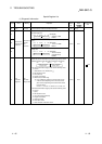
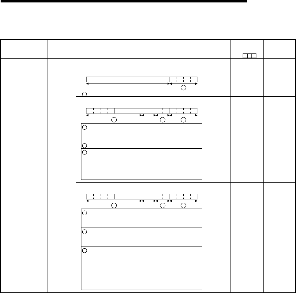
• The switch status of the remote I/O module is stored in the following
format.
B15 B4B3 B0
1
Vacant
1
Remote I/O module switch status Always 1: STOP
S (Always) New Remote
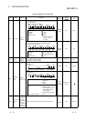
• The CPU module switch status is stored in the following format:
B15 B12B11 B8 B7 B4B3 B0
Vacant
3 2
1
1
: CPU switch status
0: RUN
1: STOP
2: L.CLR
2
: Memory card switch Always OFF
3
: DIP switch B8 through BC correspond to SW1
through SW5 of system setting
switch 1.
0: OFF, 1: ON
BD through BF are vacant.
S(Every
END
processing)
New QCPU
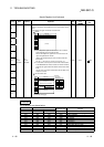
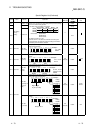
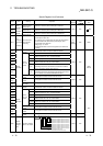
• The CPU module switch status is stored in the following format:
B15 B12B11 B8 B7 B4B3 B0
Vacant
3 2
1
1
: CPU key
Status of switch
0 : RUN
1 : STOP
2 : L.CLR
2
: Memory cards switch
B4 corresponds to card A, and B5
corresponds to card B
OFF at 0; ON at 1
3
: DIP switch
B8 through B12 correspond to
SW1 through SW5 of system
setting switch 1.
B14 and B15 correspond to SW1
and SW2 of system setting switch
2, respectively.
OFF at 0; ON at 1
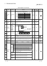
SD200
Status of
switch
Status of CPU
switch
S(Every
END
processing)
New QnA