


9 - 5 9 - 5
MELSEC-Q
9 LOADING AND INSTALLATION
(3) Fail-safe measures against failure of the PLC
Failure of a CPU module or memory can be detected by the self-diagnosis
function. However, failure of I/O control area may not be detected by the CPU
module.
In such cases, all I/O points turn ON or OFF depending on a condition of
problem, and normal operating conditions and operating safety cannot
sometimes be maintained.
Though Mitsubishi PLCs are manufactured under strict quality control, they may
cause failure or abnormal operations due to unspecific reasons. To prevent the
abnormal operation of the whole system, machine breakdown, and accidents,
fail-safe circuitry against failure of the PLC must be constructed outside the PLC.
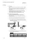
Examples of a system and its fail-safe circuitry are described below:
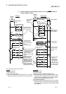
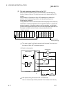
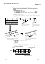
<System example>
Power supply
module
CPU module
Input 16 points
Vacant
Input 16 points
Input 16 points
Input 16 points
Output 16 points
Y80 to Y8F
Output 16 points
Output 16 points
Output 16 points
Output 16 points
Output module for
fail-safe purpose 1
Power supply
module
1: The output module for fail-safe purpose should be loaded in the last slot of
the system. (Y80 to Y8F in the above system.)
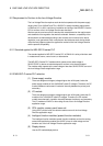
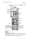
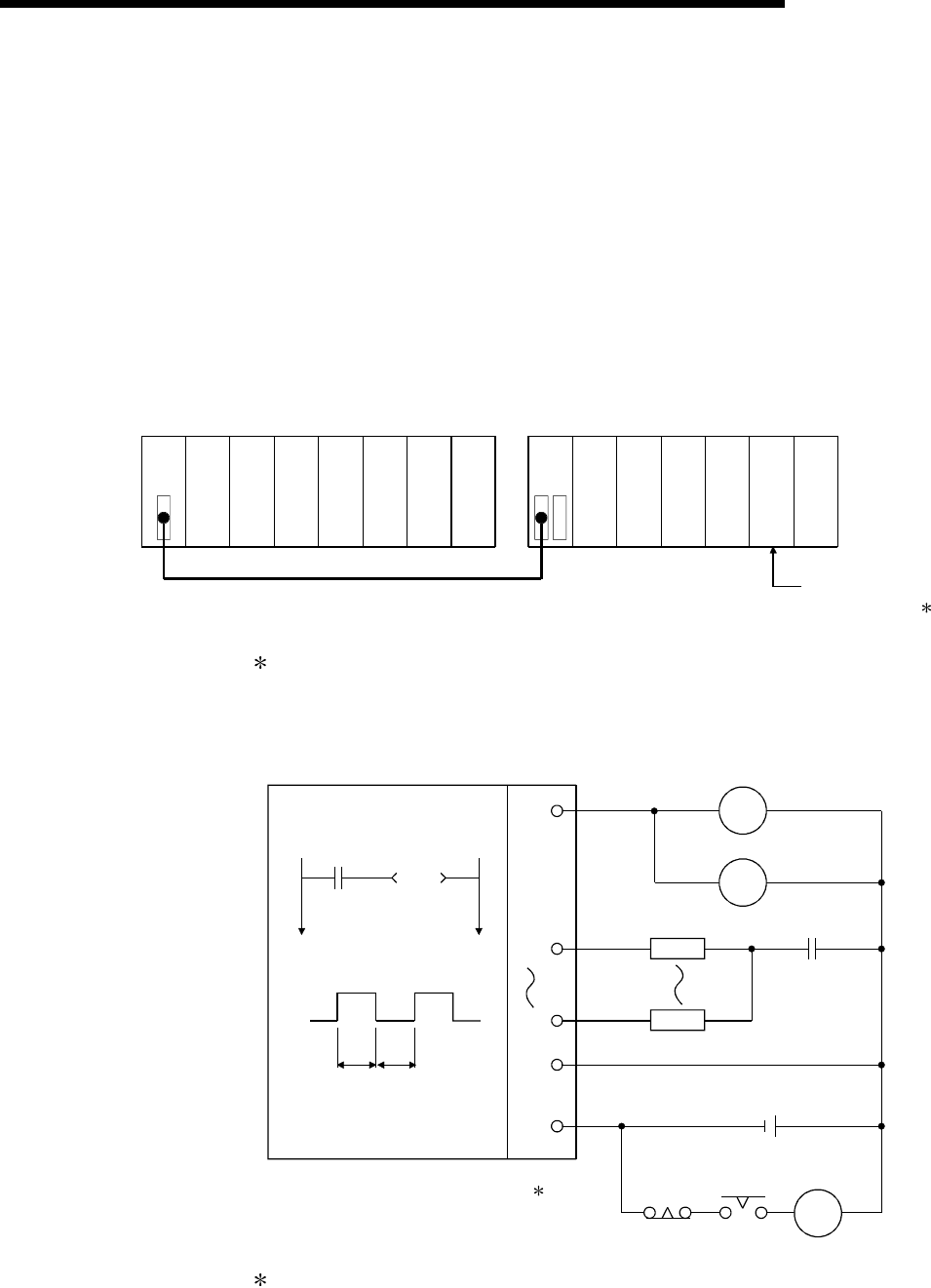
<Fail-safe circuit example>
Internal program
SM412
T1
ON delay timer
1s
T2
OFF delay timer
1s
L
L
MC
T2T1
+
-
24V DC
Y80
Y81
Y8F
24V
0V
Y80
Y80
External load
0.5s0.5s
CPU module
MC
Output module
2
2: Y80 repeats turning ON and then OFF at 0.5s intervals.
Use a no-contact output module (transistor in the example shown above).