


9 - 2 9 - 2
MELSEC-Q
9 LOADING AND INSTALLATION
!
DANGER
When connecting a peripheral device to the CPU module or connecting
a personal computer or the like to the special function module to
exercise control (data change) on the running PLC, configure up an
interlock circuit in the sequence program to ensure that the whole
system will always operate safely.
Also before exercising other control (program change, operating status
change (status control)) on the running PLC, read the manual carefully
and fully confirm safety.
Especially for the above control on the remote PLC from an external
device, an immediate action may not be taken for PLC trouble due to a
data communication fault.
In addition to configuring up the interlock circuit in the sequence
program, corrective and other actions to be taken as a system for the
occurrence of a data communication fault should be predetermined
between the external device and PLC CPU.
!
CAUTION
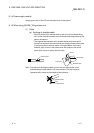
Do not bunch the control wires or communication cables with the main
circuit or power wires, or install them close to each other. They should
be installed 100 mm (3.94 inch) or more from each other.
Not doing so could result in noise that would cause erroneous
operation.
When controlling items like lamp load, heater or solenoid valve using an
output module, large current (approximately ten times greater than that
present in normal circumstances) may flow when the output is turned
OFF to ON. Take measures such as replacing the module with one
having sufficient rated current.
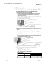
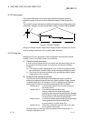
When the PLC power supply is switched ON-OFF, correct control output may not be
performed temporarily due to differences in delay time and starting time between the
PLC power supply and the external power supply for the controlled object (especially
DC).
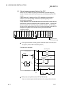
For example, if the external power supply for the controlled object is switched on in a
DC output module and then the PLC power supply is switched on, the DC output
module may provide false output instantaneously at power-on of the PLC. Therefore, it
is necessary to make up a circuit that can switch on the PLC power supply first.
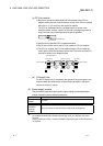
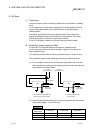
Also, an abnormal operation may be performed if an external power supply fault or
PLC failure takes place.
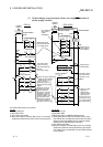
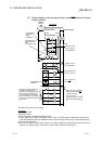
To prevent any of these abnormal operations from leading to the abnormal operation of
the whole system and in a fail-safe viewpoint, areas which can result in machine
breakdown and accidents due to abnormal operations (e.g. emergency stop, protective
and interlock circuits) should be constructed outside the PLC.
The following page gives examples of system designing in the above viewpoint.
9