


9 - 12 9 - 12
MELSEC-Q
9 LOADING AND INSTALLATION
9.3.2 Instructions for mounting the base unit
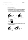
When mounting the PLC to an enclosure or similar, fully consider its operability,
maintainability and environmental resistance.
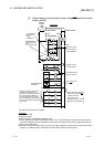
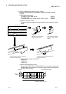
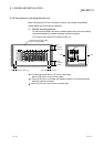
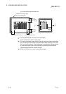
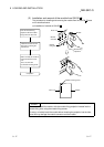
(1) Module mounting position
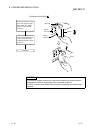
For enhanced ventilation and ease of module replacement, leave the following
clearances between the module top/bottom and structure/parts.
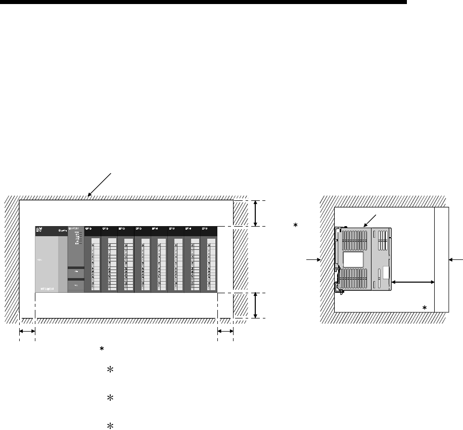
(a) In case of main base unit or extension base unit
Indicates the panel top, wiring
duct or any part position.
PLC
DoorPanel
20mm
(0.79 inch)
or more 3
5mm (0.20 inch) or more 2
5mm (0.20 inch) or more
30mm
(1.18 inch)
or more 1
30mm
(1.18 inch)
or more
1 : For wiring duct with 50mm (1.97 inch) or less height.
40mm (1.58 inch) or more for other cases.
2 : 20mm (0.79 inch) or more when the adjacent module is not removed and the
extension cable is connected.
3 : 80mm (3.15 inch) or more for the connector type.