


EN-76
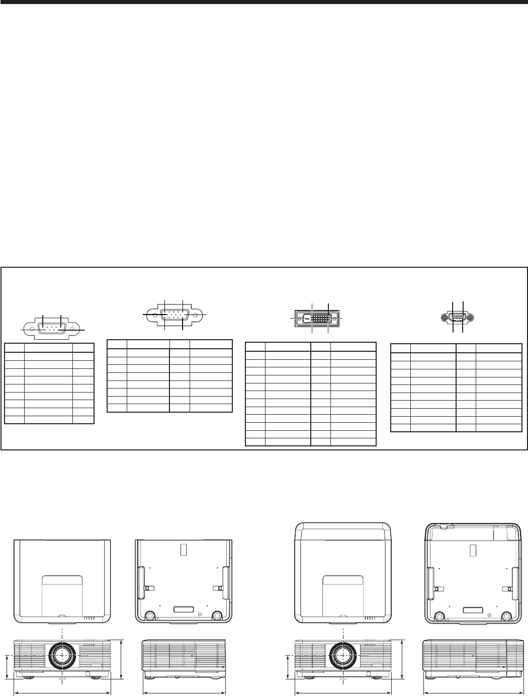
490
201
119*
421
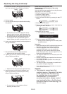
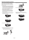
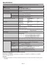
Dimension drawings (unit: mm)
Specifications (continued)
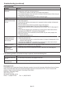
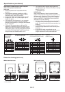
Specification of RGB signals in each computer
mode of the projector (continued)
Important:
• Some computers aren’t compatible with the
projector.
• The projector’s maximum resolution is 1280 x
800 pixels. It may not display images of higher
resolutions than 1280 x 800 correctly.
• Images with SYNC on G (Green) signal may jitter.
• Images with SYNC on G (Green) signal may be
tinged with green.
• If the resolution and frequency of your computer
aren’t shown on the table, find the compatible
resolution and frequency by changing the resolution
of your computer.
•
TV60 and TV50 are equivalent to 480i and 576i
respectively. When these signals are supplied to the
VIDEO IN or S-VIDEO IN terminal, the signal mode is
indicated as TV60 or TV50. When they are supplied to
the COMPUTER/COMPONENT VIDEO IN terminals,
the signal mode is indicated as 480i or 576i.
• Thisprojectordoesn’tsupport480psignalsfrom
video devices having 4 lines (R, G, B, CS*) or having 5
lines (R, G, B, H, V).
* : Composite Sync
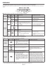
NATIVE mode
When moire patterns or lines of uneven thickness
appear on the projected image, these symptoms may
be improved by displaying it in its original image size
(NATIVE mode). To display the image in the NATIVE
mode, set ASPECT of the SIGNAL menu to NATIVE.
(See page 31 for menu setting.)
• Forsignalsthatarelargerthanthepanelresolution,
only their center part is displayed in the NATIVE
mode. The area exceeding the panel resolution isn’t
displayed.
• IntheNATIVEmode,imagesareblack-framed
when the image resolution is lower than the panel
resolution.
• IntheNATIVEmode,somesignalsmaybe
displayed with a black frame even when they have
a higher resolution than the panel resolution.
490
506
201
119*
Without terminal cover
With terminal cover
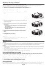
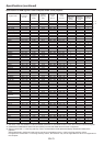
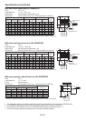
Connectors
SERIAL IN/OUT
(D-SUB 9-pin)
15
6
9
Pin No.
Name I/O
1 – –
2 TXD IN
3 RXD OUT
4 – –
5 GND –
6 – –
7 – –
8 – –
9 – –
COMPUTER/COMPONENT VIDEO
IN-1 (Mini D-SUB 15-pin)
15
11
6
10
15
Pin No.
Spec.
Pin No.
Spec.
1 R(RED)/P
R
/C
R
9 DDC 5V
2 G(GREEN)/Y 10 GND
3 B(BLUE)/P
B
/C
B
11 GND
4 GND 12 DDC Data
5 GND 13 HD/CS
6 GND 14 VD
7 GND 15 DDC Clock
8 GND
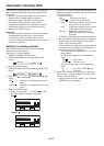
COMPUTER/COMPONENT VIDEO
DVI-D IN (HDCP)
(DVI-D 24-pin
)
1724
16
9
8
1
Pin No.
Spec.
Pin No.
Spec.
1 TMDS DATA 2- 13
-
2 TMDS DATA 2+ 14
+5V Power
3
TMDS DATA 2 Shield
15
Ground (for +5V)
4
-
16 Hot Plug Detect
5
-
17 TMDS DATA 0-
6 DDC Clock 18 TMDS DATA 0+
7 DDC Data 19
TMDS DATA 0 Shield
8
-
20
-
9 TMDS DATA 1- 21
-
10 TMDS DATA 1+ 22
TMDS Clock Shield
11
TMDS DATA 1 Shield
23 TMDS Clock+
12
-
24 TMDS Clock-
HDMI IN
(HDMI 19-pin)
19
1
2
18
Pin No.
Spec.
Pin No.
Spec.
1
TMDS Data2+
11
TMDS Clock Shield
2
TMDS Data2 Shield
12
TMDS Clock-
3
TMDS Data2-
13
CEC
4
TMDS Data1+
14
–
5
TMDS Data1 Shield
15
SCL
6
TMDS Data1-
16
SDA
7
TMDS Data0+
17
DDC Ground
8
TMDS Data0 Shield
18
+5 V Power
9
TMDS Data0-
19
Hot Plug Detect
10
TMDS Clock+
*: Factory-defaults