


MTASR1-100 Owner’s Manual
20
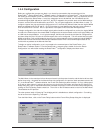
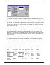
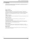
The next frame relay parameter to consider is the Committed Information Rate (CIR) and the Excess Burst
Rate (Be). The total CIR and Be for all the DLCIs at a particular site can not exceed the port capacity. During
subscription, the local service provider established that each virtual circuit could run at 64,000 bit-per-second,
so for the Mounds View site the port capacity is 128K bandwidth. This allows up to 64K for each DLCI which
could translate into a CIR of 64000 and a Be of zero or maybe a better combination would be a CIR of 56000
and a Be 9000. This last combination of 56K and 9K may provide less congestion on the frame relay network.
The final frame relay parameter is Mode. The Mode depends on how you set up the CIR and Be. If you have
a value in both the CIR and Be fields, then the best mode would be Adhere to CIR + Be or you could choose
the As Fast as Possible option.
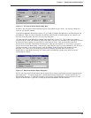
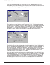
To add DLCI 50, click on the Add button. To map DLCI 51 to its protocol stack, click on the DLCI numeric
dialog box and enter 51. Then click on the IP Address check box. When the WAN IP addresses appear in the
drop down menu, you will notice that the address for logical WAN 1 no longer appears. Click on the logical
WAN 2 address 200.2.10.1. Then set the CIR and Be values for logical WAN 2. Set the Mode and click on
the Add button to map DLCI 51. Now you can click on the OK button and return to the Main menu. Click on
the Download Setup button and the setup utility is ready to download the frame relay configuation to the
RouteFinder
100
. The RouteFinder
100
is automatically rebooted. The Windows software returns to the Program
Manager screen and when the FAIL light on the RouteFinder
100
goes off, it is ready to transfer data over the
frame relay network.
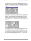
To configure the River Falls and Minneapolis sites, you follow the same process as we just went thru only you
only have to consider one logical WAN and DLCI for each site.
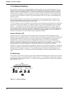
The following listing ties the Mounds View LAN to its logical WANs, maps the logical WANs to their DLCI,
provides the virtual path through the frame relay network to their respective remote site. Following the
Mounds View example, space is provided for you to fill in your host site address, logical WAN address, DLCI,
and if you have your PVC number from your local service provider. Continuing on is the remote site
information for this virtual path. A point to remember here is that the logical WAN has to be in the same
network in order for this to work and that no LAN can have the same address.
Mounds View Site River Falls Site
LAN 1 IP Logical WAN 1 DLCI Local Remote DLCI WAN 1 LAN 2 IP
Address Address PVC PVC Address Address
200.2.8.1 200.2.9.1 50 16 26 52 200.2.9.2 200.2.11.1
Your Host Site Its Remote Site
LAN 1 Logical WAN 1 DLCI Local Remote DLCI WAN 1 LAN 2
Address Address PVC PVC Address Address
_________ __________ ___ ____ ____ ___ _______ _______
Mounds View Site Minneapolis Site
LAN 1 IP Logical WAN 2 DLCI Local Remote DLCI WAN 1 LAN 3 IP
Address Address PVC PVC Address Address
Same IP 200.2.10.1 51 17 27 53 200.2.10.2 200.2.12.1
Your Host Site Its Remote Site
LAN 1 Logical WAN 2 DLCI Local Remote DLCI WAN 1 LAN 3
Address Address PVC PVC Address Address
Same Addr __________ ___ ____ ____ ___ ________ _________