


9-16
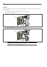
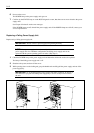
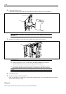
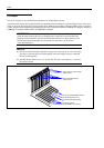
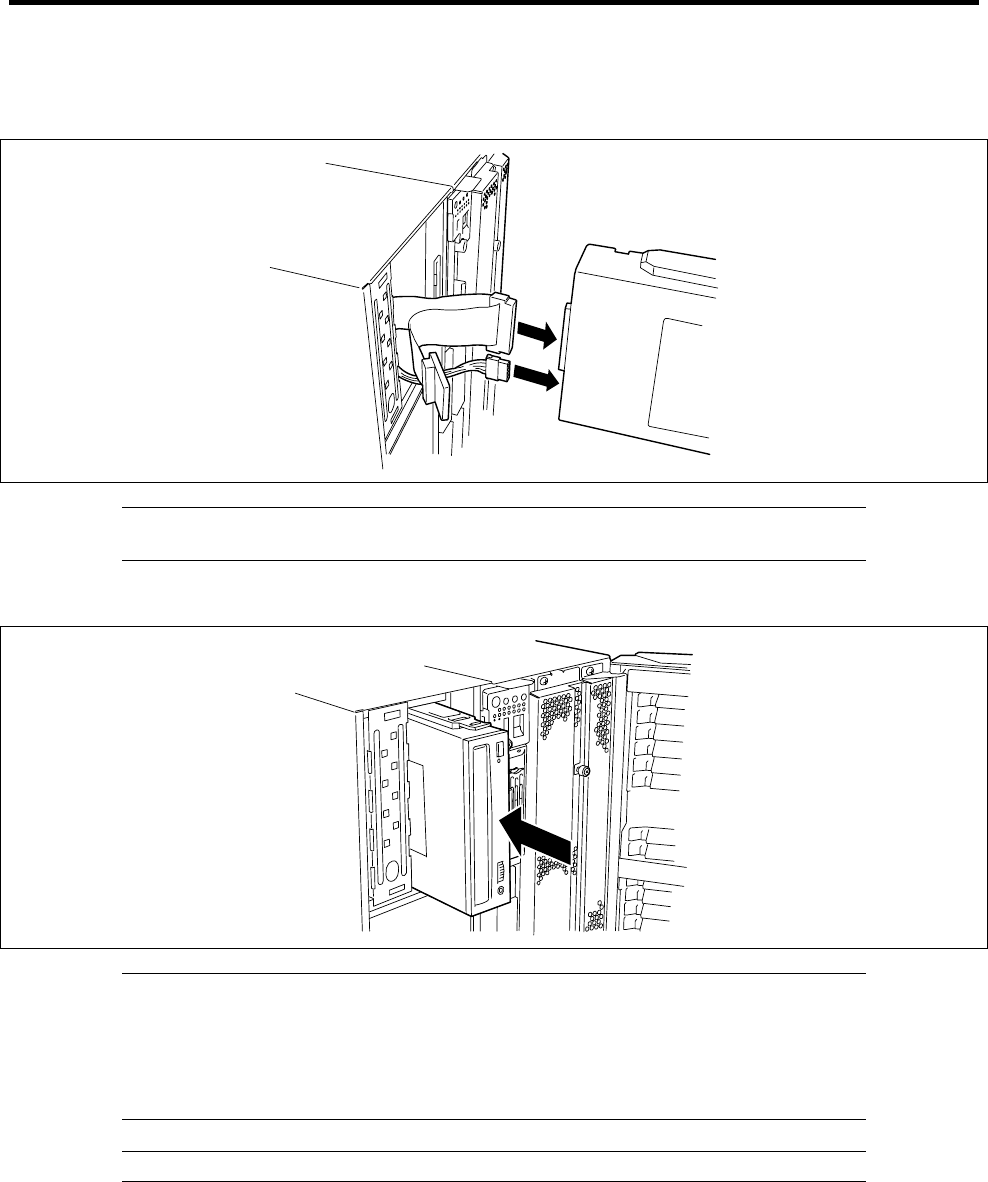
6. Connect the interface cable.
Connect the SCSI and power cables secured in the 5.25-inch device bay to the 5.25-inch device.
IMPORTANT: A connector cap is attached to the power cable. Keep the removed cap for
future use.
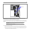
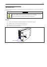
7. Push the 5.25-inch device to the device bay carefully until a click occurs to lock it.
IMPORTANT:
If the SCSI connector "Ch-B" is connected to the additional HDD cage, install the
optional SCSI controller board to connect with the 5.25-inch device.
Connector pin bending or incomplete connection may cause a malfunction to occur.
Provide the connection securely watching the 5.25-inch device and cable connectors.
NOTE: Make sure that the cable is not caught.
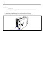
8. Close the front door.
9. Provide the setup for the SCSI controller.
If the 5.25-inch device is connected to optional SCSI controller board, refer to the manual that comes with the
SCSI controller board for setup.
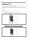
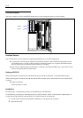
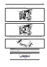
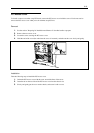
Removal
Remove the 5.25-inch device in the reverse procedure of the installation.