User Manual for the NETGEAR 7200 Series Layer 2 Managed Switch Software
6-8 Quick Startup
202-10010-01
VLAN Configuration Example
This section provides configuration examples for VLAN configurations.
LAN switches can segment networks into logically defined virtual workgroups.This logical
segmentation is commonly referred as a virtual LAN (VLAN). This logical segmentation of
devices provides better LAN administration, security, and management of broadcast activity over
the network. Virtual LANs have become an integral feature of switched LAN solutions.
The VLAN example below demonstrates a simple VLAN configuration with a GSM7224 Layer 2
Managed Switch.
If a single port is a member of VLANs 2, 3 and 4, the port expects to see traffic tagged with either
VLAN 2,3 or 4.
The PVID (Port Virtual Identification) could be something entirely different, for example '12' and
things would still work fine, just so incoming traffic was tagged.
Example:
• Project A = (VLAN2, ports 1,2)
• Project B = (VLAN3, ports 3,4)
• Project C = (VLAN4, ports 5,6)
• Project P = (VLAN 9, port 7)
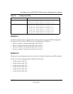
Table 6-9. Creating the VLANs
VLAN Command
create VLAN 2 config vlan create 2
config vlan participation include 2 0.1
config vlan participation include 2 0.2
create VLAN 3 config vlan create 3
config vlan participation include 3 0.3
config vlan participation include 3 0.4


