7
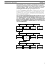
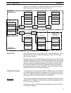
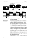
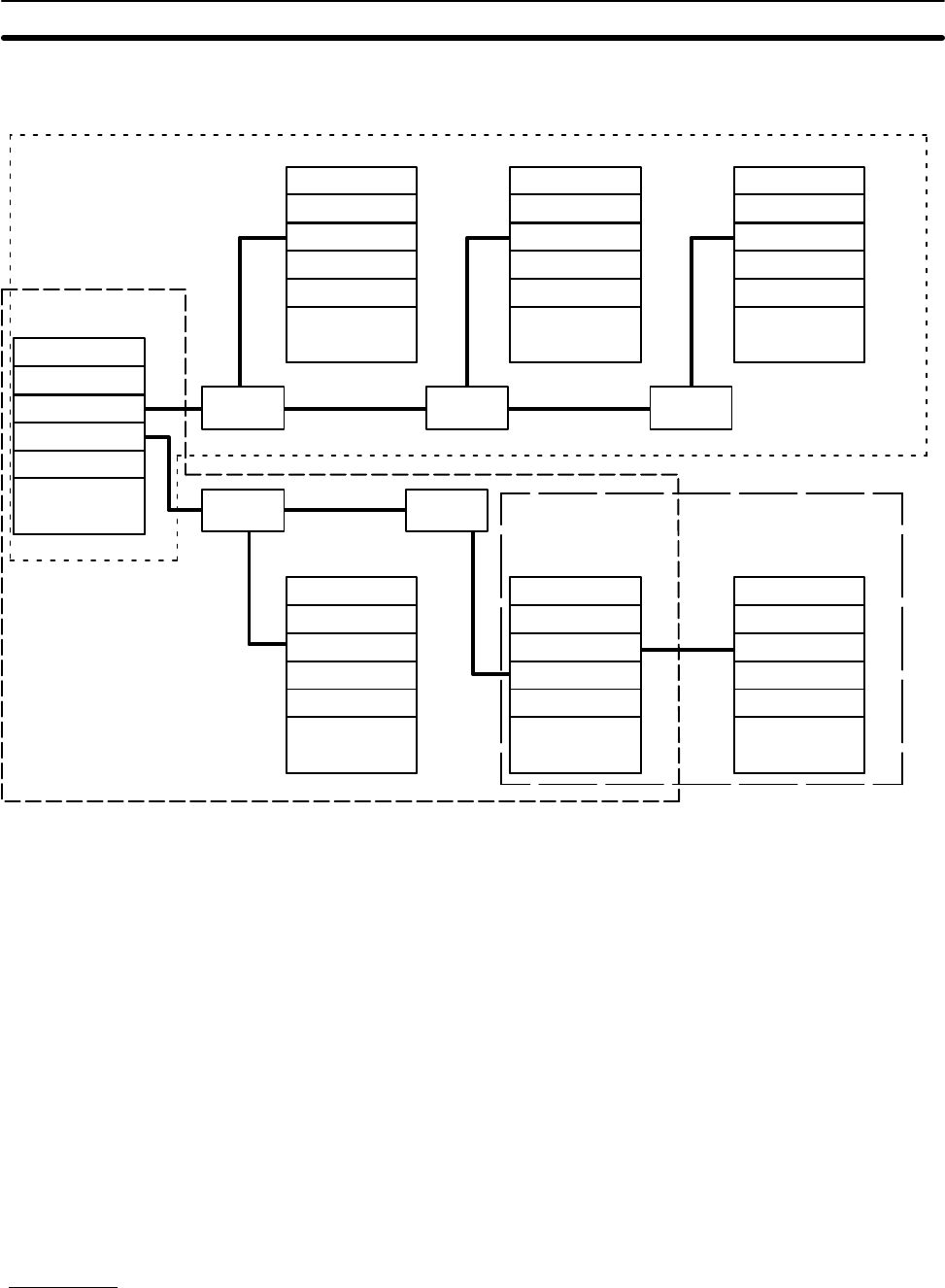
Note that a Link Adapter is not used in Subsystem 3. As explained above, it
does not require any because it contains only two PCs.
CPU Rack
CPU Rack
PC Link Unit
PC Link Unit
CPU
Link
Adapter
PC Link Unit
PC Link Unit
CPU
CPU Rack
PC Link Unit
CPU
CPU Rack
PC Link Unit
CPU
CPU Rack
PC Link Unit
CPU
CPU Rack
PC Link Unit
CPU
CPU Rack
PC Link Unit
CPU
Link
Adapter
Link
Adapter
Link
Adapter
Link
Adapter
Subsystem 1
operating level 1
Subsystem 2
operating level 0
Subsystem 3
operating level 1
A PC that has two PC Link Units mounted to it is called a transfer PC. This is
because it can be used to transfer data between the two PC Link Subsys-
tems to which it belongs.
Although all the PCs in the same Subsystem automatically have data written
into their LR areas from the PCs in the same Subsystem, this is not the case
with PCs in different Subsystems. A PC that belongs to two Subsystems can,
however, transfer data between Subsystems by reading it from any part of
the LR words it shares with one of the Subsystems and writing the data to
the words allocated it in the other Subsystem. This transfer operation is pro-
grammed by the user in the normal user program.
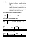
The total length of wire cable (e.g., RS-485 or RS-422) must not exceed 500
m. Individual branch lines from Link Adapters to PC Link Units must not ex-
ceed 10 m. Greater transmission distances can be achieved by using optical
links between PC Link Units (see Section 2 Link Adapters).
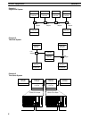
The following examples demonstrate some of the ways that PCs can be con-
nected in PC Link Systems. Example 3 also provides the appearance two of
the CPU Racks in the System.
An example of a PC Link System designed using optical links is provided in
2-2 Using Link Adapters.
Transfer PCs
Transmission Distance
Examples
System Configuration Section 2-1


