24
4-1 C200H PC Link Units
4-1-1 Nomenclature, Switches, and Indicators
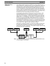
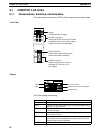
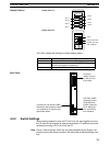
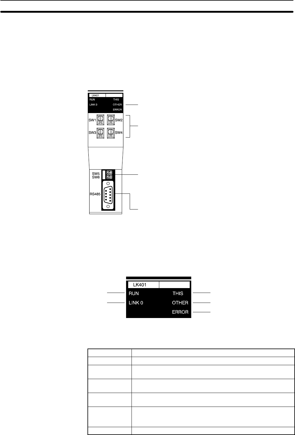
The basic names and functions of PC Link Unit components are given below.
Display
Indicates operational status.
Switches 1 through 4
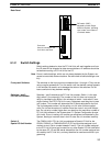
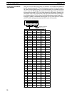
Used to set the PC Link Unit unit number,
the Special I/O Unit unit number, and the
number of LR bits in the Subsystem.
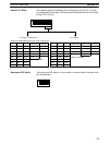
Switches 5 and 6
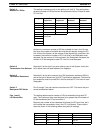
Used to set the type of transmission
line and termination resistance.
RS-485 connector
Used to connect the PC Link Unit
to another PC Link Unit or to a
Link Adapter.
RUN
Unit 0
This PC Link Unit
Another PC Link Unit in the System
Error indicator
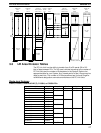
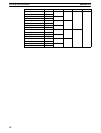
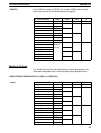
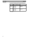
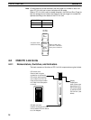
The LEDs indicate the following :
LED Function/Meaning
RUN Lit when PC Link Units are operating.
LINK 0 Lit when PC Link Unit #0 (polling unit) is operating properly. Not lit
when an error has occurred.
THIS Lit when this PC Link Unit is operating properly. Not lit when an
error has occurred.
OTHER Lit when other PC Link Units are operating properly. Not lit when
an error has occurred.
ERROR Light when a unit number is set incorrectly; flashes when an error
has occurred on the links between #0 or others and this PC Link
Unit. Not lit during normal operation.
All LEDs not lit. All LEDs will go out when an error occurs in the PC.
Front Panel
Display
C200H PC Link Units Section 4-1


