27
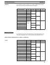
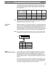
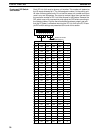
The following table shows the number of scans of delay in communication
produced by various numbers of refresh bits and LR bits. The delays given
are for Single-level Systems. Delays in Multilevel Systems would be half of
those shown below.
No. of re-
fresh bits
No. of
LR bits
64 128 256 512
32 16 8 4 4
64 16 8 4 4
128 –– 8 4 4
256 –– –– 4 2
512 –– –– –– 2
The IORF (97) instruction can be used in programming to refresh LR bits at
particular points in a programming if current LR data is required. Refer to the
Operation Manual for your CPU Unit for details.
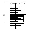
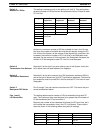
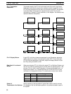
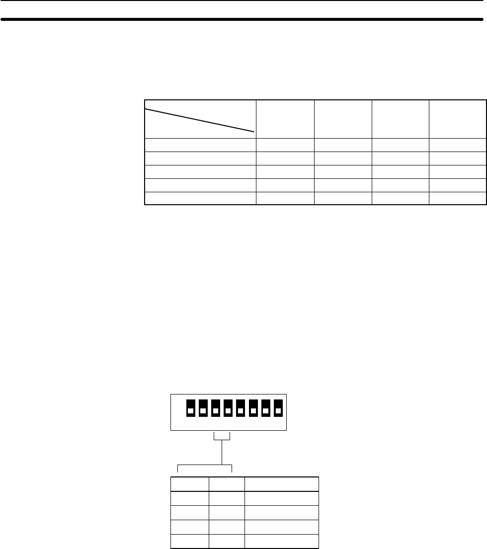
When mounting two PC Link Units to the same PC in a Multilevel System, set
one PC Link Unit for operating level 0 and the other for operating level 1. Set
all PC Link Units in each Subsystem to the same operating level. If all PCs in
the System have only one PC Link Unit mounted to them, set all Units for a
Single-level System. There is no difference in the first two settings. Operating
Level flags, AR 2411 and AR 2412, can be used to check operating levels.
An error indication will not be made even if two PC Link Units with the same
Subsystem are mounted to the same PC; set and check the pins with care.
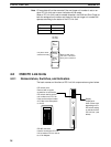
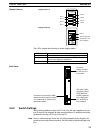
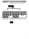
ON
12345678
3 4 Setting
ON ON Single-level
ON OFF Single-level
OFF ON Multilevel, level 1
OFF OFF Multilevel, level 0
SW7
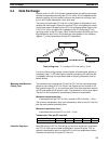
Pin 8 on switch 7 can be turned on to allocate twice the normal number of
words to any polled unit. This is not possible for a polling unit, which will be
allocated the normal number of words regardless of the setting of pin 8.
If pin 8 is left off, the PC Link Unit will be allocated the number of words indi-
cated by setting of switch 4. The actual words will be determined by the unit
number.
If pin 8 is turned on, the PC Link Unit will be allocated the words both for its
unit number and for the next larger unit number, i.e., it will be allocated twice
the number of words set on switch 4. If pin 8 is set for double allocation, do
not use the next larger number for any other PC Link Unit.
Note
Pins 3 and 4:
Levels
Note
Pins 8:
Double Allocation Setting
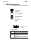
C200H PC Link Units Section 4-1


