


33
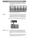
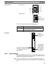
4-3 Switch Setting Example
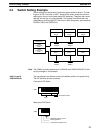
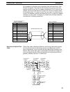
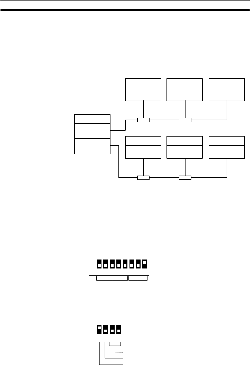
Switch settings for the following System are given below for level 0. The set-
tings for all PC Link Units in level 1 would be the same, except for the level
setting (pins 3 and 4 on the back-panel DIP switches). These are the normal
settings, but not the only ones possible. The System is multilevel with two
Subsystems, contains eight PC Link Units in each Subsystem, and combines
C2000H, C500, and C200H PCs.
C500 PC
Unit 1,
level 1
C2000H PC
Unit 0
(polling unit),
level 0
Unit 2,
level 1
Unit 3,
level 1
C500 PC C200H PC
C500 PC
Unit 1,
level 0
Unit 2,
level 0
Unit 3,
level 0
C500 PC C200H PC
Unit 0
(polling unit),
level 1
Link
Adaptor
Link
Adaptor
Link
Adaptor
Link
Adaptor
The C200H could be replaced by the C200HS and C200HX/HG/HE(-Z) with-
out any changes in this example.
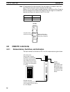
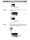
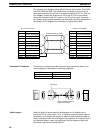
The transmission line selector is set to the bottom position (no optical links).
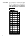
The DIP switches are set as follows:
Front-panel DIP Switch
ON
12345678
64 transfer LR bits
Unit 0
SW1
Back-panel DIP Switch
ON
1234
SW3
Multilevel System, level 0
Display pattern A
Termination resistance ON
Note
Unit 0, Level 0
C500-LK009-V1
Switch Setting Example Section 4-3