


47
The equation for minimum I/O response time is thus as follows:
Response time = input ON delay + scan time of PC of Unit 0 + minimum
transmission time + scan time of PC of Unit 7 + output ON
delay
Inserting the following values into this equation produces a minimum I/O re-
sponse time of 99 ms.
Input ON delay 1.5 ms
Output ON delay 15 ms
Scan time of PC of Unit 0 20 ms
Scan time of PC of Unit 7 50 ms
Minimum transmission time 12.5 ms (for 8 Units transferring 64 bits
each)
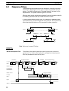
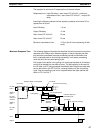
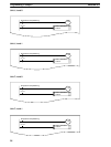
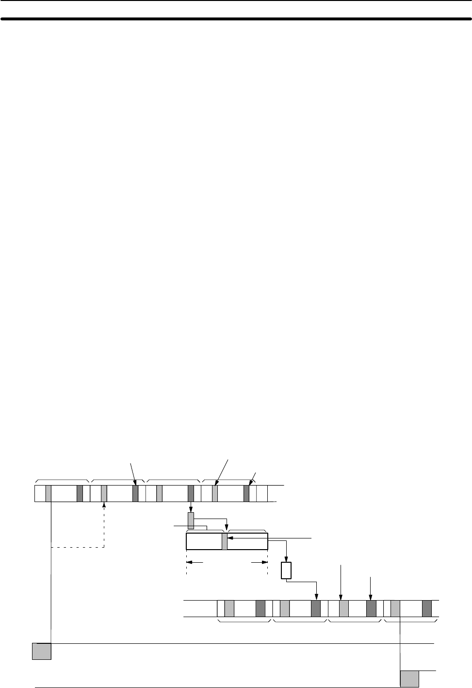
The following diagram illustrates the data flow that will produce the maximum
response time. Delays occur because signals or data is received just after
they would be processed, because processing cannot be finished at one
time, or because data is sent during processing. In all cases, processing
must wait until the next scan/polling cycle.
First output to the buffer in the polling unit is delayed because all of the data
could not be loaded into the buffer at once. The polling delay is the result of
the LR data in its PC being updated immediately after the previous data was
sent to the buffer in the PC Link Unit, causing a delay until the next polling
cycle. One more polling cycle is then required before the data reaches the
buffer in PC Link Unit 7.
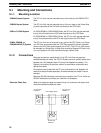
Induction sequence
processing time
Scan time
PC with
Unit 0
Buffer in
Unit 0
PC Link
Unit trans-
missions
Buffer in
Unit 7
Input
Output
Maximum
Transmis-
sion time
Scan time
I/O refresh
PC Link Unit servicing
PC Link polling time
Polling delay
Output to buffer not completed.
I/O refresh
PC Link Unit servicing
PC with
Unit 7
Maximum Response Time
Response Times Section 6-1