


32
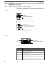
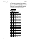
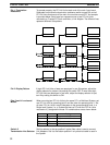
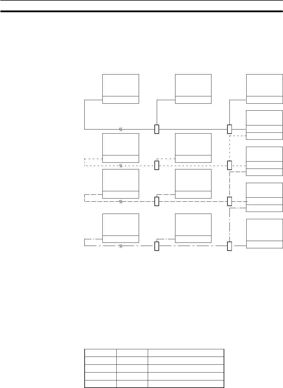
To operate properly, the PC Link Unit at each end of the main line of each
Subsystem must have the termination resistance switch turned ON, and all
PC Link Units that branch off the main line must be turned OFF. An example
is provided below. Each large box represents one or two PC Link Units
mounted to a C-series PC; each small box; a Link Adapter. The different lines
represent different Subsystems.
Resistance ON
Resistance OFF
Resistance ON
Resistance OFF
Resistance ON
Resistance OFF
Resistance ON
Resistance OFF
Resistance OFFResistance ON
Resistance OFFResistance ON
Resistance OFFResistance ON
Resistance OFFResistance ON
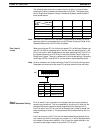
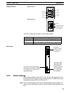
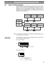
If eight PC Link Units or fewer are employed in one Subsystem, adjust the
display selector for pattern A by setting this switch OFF. If more than eight
PC Link Units are employed in one level, adjust the display selector for pat-
tern B by setting this switch to ON.
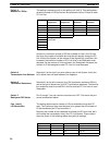
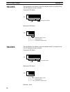
When mounting two PC Link Units to the same PC in a Multilevel System, set
one PC Link Unit for operating level 0 and the other for operating level 1. Set
all other PC Link Units in each Subsystem to the same operating level. In a
Single-level System (i.e., a System that has no PC with two PC Link Units
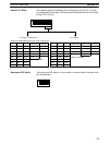
mounted to it), designate the mode. Pin combinations are as shown below.
3 4 Setting
ON ON Single-level, LK009 mode
ON OFF Single-level, LK003 mode
OFF ON Multilevel, level 1
OFF OFF Multilevel, level 0
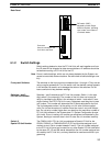
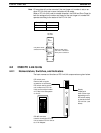
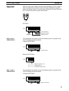
Set this selector to the top position if optical fiber cable is used to connect
Link Adapters. Set it to the bottom position if only electrical cable is used in
the System.
Pin 1: Termination
Resistance
Pin 2: Display Pattern
Pins 3 and 4: Levels and
Modes
Switch 2:
Transmission Line Selector
C500 PC Link Units Section 4-2