


40
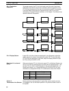
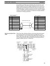
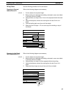
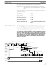
Pin connections for Systems using optical links are shown below. Twist SDB
with SDA; RDA with RDB. The shield wire is connected only at one end of
each cable to prevent current flow. For cables connecting a PC Link Unit to a
Link Adapter, connect the shield wire to FG at the PC Link Unit connector
(either the connector hood, if it is metal, or pin #7 can be used). Connector
pin numbers and connector assembly are described in following subsections.
See Section 2 Link Adapters for information on optical fiber cables.
Shielded twisted pair cable
PC Link Unit connector AL004(-P) Link Adapter
Pin no. Signal name
1 Transfer data B (RDB)
2
3
4
5 Send data B (SDB)
6 Receive data A (RDA)
7 Frame ground (FG)
8
9 Send date A (SDA)
Hood Frame ground (FG)
Pin no. Signal name
1 Receive data B (RDB)
2
3
4
5 Send data B (SDB
6 Receive data A (RDA)
7 Frame ground (FG)
8
9
Hood Frame ground (FG)
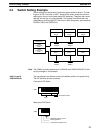
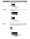
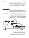
Connector pin numbers and cable-connector layout are shown below. Con-
nector assembly is described in a following subsection.
Connector XM2A-0901
Housing XM2S-0911
Maker OMRON
Connectors
Cable (shielded twisted-pair
cable recommended)
5
4
3
2
1
9
8
7
6
1
2
3
4
5
6
7
8
9
Pin no. Pin no.
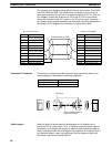
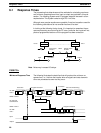
Keep the length of the connecting cable between a Link Adapter and a
branched PC Link Unit to within 10 m. In Systems employing optical fiber ca-
ble between Link Adapter, the lengths of electrical cable should be made as
short as possible to take full advantage of the properties of the optical links. If
only electrical cable is used, the total length of all the cables on both main
and branch lines must not exceed 500 m.
Connector Pin Numbers
Cable Lengths
Mounting and Connections Section 5-1