


34
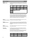
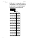
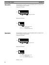
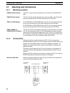
The transmission line selector is set to the bottom position (no optical links).
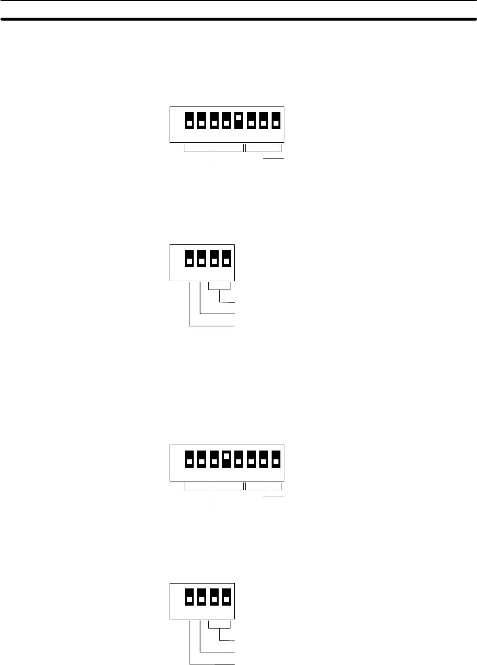
The DIP switches are set as follows:
Front-panel DIP Switch
ON
12345678
Setting not necessary
Unit 1
SW1
Back-panel DIP Switch
ON
1234
SW3
Multilevel System, level 0
Display pattern A
Termination resistance OFF
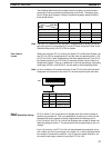
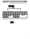
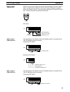
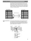
The transmission line selector is set to the bottom position (no optical links).
The DIP switches are set as follows:
Front-panel DIP Switch
ON
12345678
64 transfer LR bits
Unit 2
SW1
Back-panel DIP Switch
ON
1234
SW3
Multilevel System, level 0
Display pattern A
Termination resistance OFF
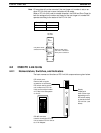
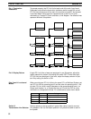
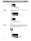
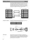
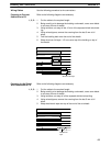
Switches 1 and 2
Unit 1, Level 0
C500-LK009-V1
Unit 2, Level 0
C500-LK009-V1
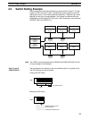
Switch Setting Example Section 4-3