


64
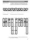
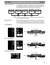
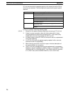
Because Unit 0 receives no response from Unit 1 only, it indicates an error
for it, and normal conditions for Units 2 and 3. Since Unit 1 receives no poll-
ing signal from Unit 0, it indicates an error for Unit 0. Units 2, 3, and 5 receive
signals from each other and indicate normal conditions other than an error for
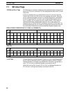
Unit 1. LED indications are shown below, as well as the conditions of the PC
RUN and Error Flags in the SR area.
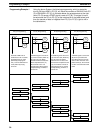
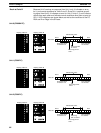
Unit 0 (C2000H PC)
1100 11110000 0010
Bit 15 Bit 0
Word 250
Error Flags OFF
for Units 2 to 5.
Error Flag OFF
for Unit 0.
PCs operative
for all Units.
Error Flag ON for
Unit 1.
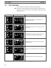
Display pattern A Display pattern B
Allocated to Unit 3.
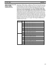
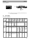
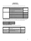
Unit 1 (C500 PC)
1100 11110000 0001
Bit 15 Bit 0
Word 62
Error Flags OFF
for Units 1 to 5.
Error Flag ON for
Unit 0.
PCs operative
for all Units.
Display pattern A Display pattern B
Allocated to Unit 3.
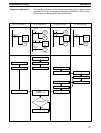
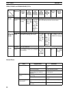
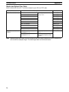
Unit 2 (C500 PC)
1100 11110000 0010
Bit 15 Bit 0
Word 62
Error Flags OFF
for Units 2 to 5.
Error Flag
OFF for Unit 0.
PCs operative
for all Units.
Error Flag ON for
Unit 1.
Display pattern A Display pattern B
Allocated to Unit 3.
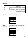
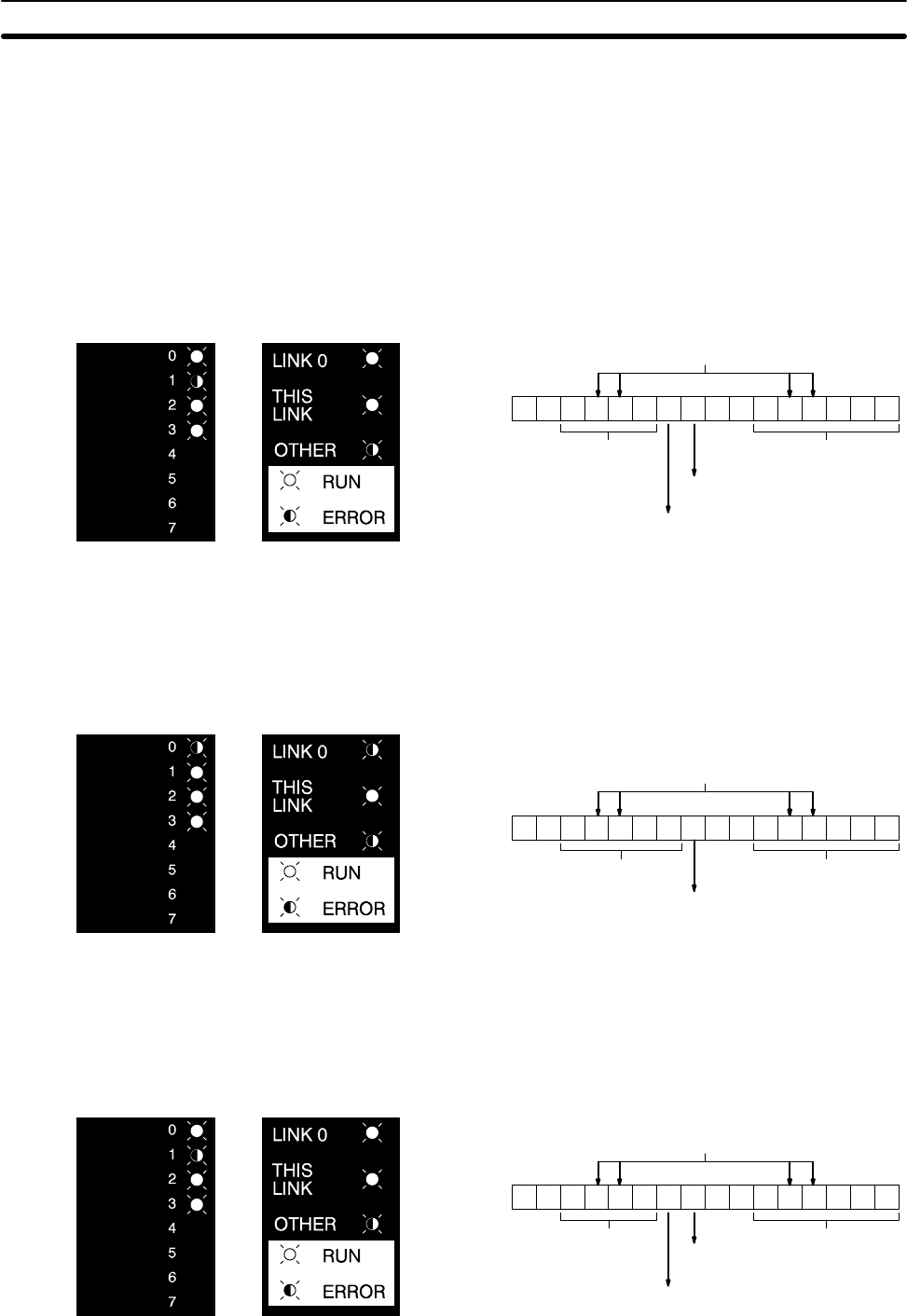
Break at Point B
Error Examples Section 7-2