


36
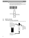
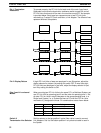
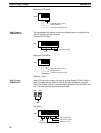
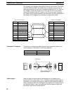
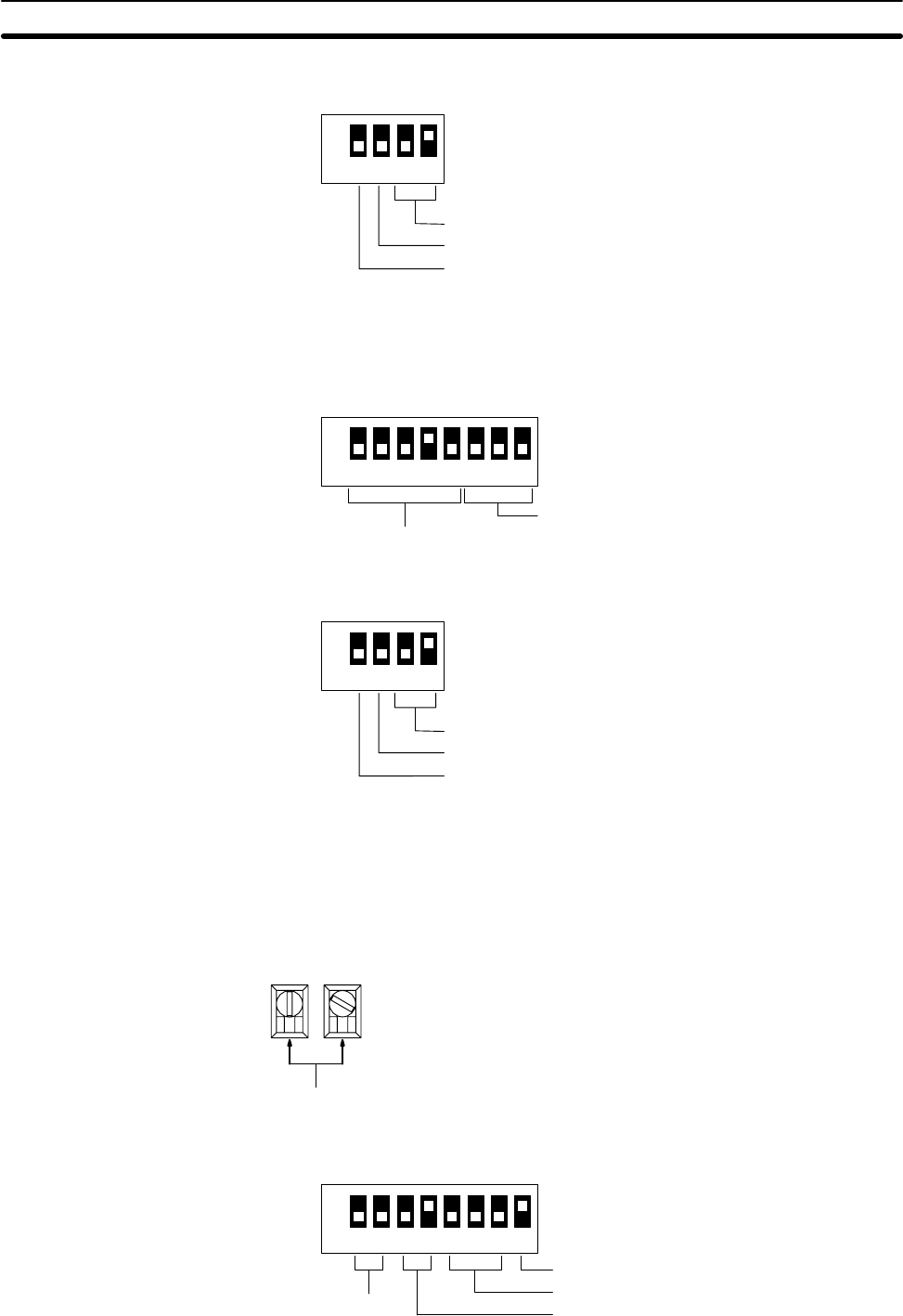
Back-panel DIP Switch
ON
1234
SW3
Multilevel System, level 1
Display pattern A
Termination resistance OFF
The transmission line selector is set to the bottom position (no optical links).
The DIP switches are set as follows:
Front-panel DIP Switch
ON
12345678
64 transfer LR bits
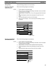
Unit 2
SW1
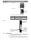
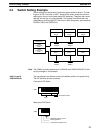
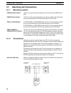
Back-panel DIP Switch
ON
1234
SW3
Multilevel System, level 1
Display pattern A
Termination resistance OFF
Switches 1 and 2
Switch 3 is set to any number not used by another Special I/O Unit. Switch 4
does not need to be set. Switch 5 is set to the right to designate no optical
links in the System. Switch 6, the termination resistance, is turned ON (to the
left). The other switches are set as shown below.
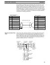
03
Unit 3
SW2SW1
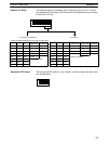
DIP Switch
ON
12345678
Multilevel, level 1
64 I/O
refresh bits
SW1
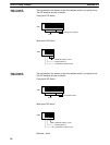
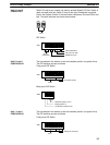
Not used, turn OFF
Normal Allocation
Unit 2, Level 1
C500-LK009-V1
Unit 3, Level 1
C200H-LK401
Switch Setting Example Section 4-3