


39
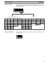
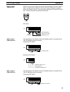
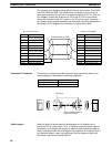
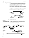
Pin connections for Systems not using optical links are shown below. Twist
DB and DA together. The shield wire is connected only at one end of each
cable to prevent current flow. For cables connecting a PC Link Unit to a Link
Adapter, connect the shield wire to FG at the PC Link Unit connector (either
the connector hood, if it is metal, or pin #7 can be used). For cables connect-
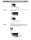
ing two Link Adapters, connect the shield wire to pin #7 at either Link Adapter
connector, but not at both. Connector pin numbers and connector assembly
are described in following subsections.
Pin no. Signal name
1
2
3
4
5 Transfer data B (DB)
6
7 Frame ground (FG)
8
9 Transfer date A (DA)
Hood Frame ground (FG)
PC Link Unit connector or
AL001 Link Adapter
Shielded twisted pair cable
AL001 Link Adapter
Pin no. Signal name
1
2
3
4
5 Transfer data B (DB)
6
7 Frame ground (FG)
8
9 Transfer date A (DA)
Hood Frame ground (FG)
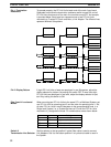
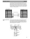
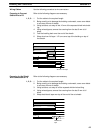
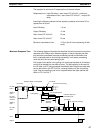
Optical fiber cable is extremely effective in eliminating malfunctions caused
by noise sources near the connecting cables or by differences in the PC
ground impedances. It also increases the total cable length allowable in the
System. When optical fiber cable is used together with electrical cables, wir-
ing is 4-conductor simplex. Wire cable sections should be kept as short as
possible, preferably less than 10 meters each.
–
+
–
+
+
–
PC Link Unit
LK009-V1
Link Adapter
AL002(-P)
Link Adapter
AL004(-P)
Link Adapter
AL004(-P)
PC Link Unit
LK009-V1
Optical fiber
cable
PC Link Unit
LK009-V1
Link Adapter
AL004(-P)
Electrical and Optical Fiber
Cable
Mounting and Connections Section 5-1