


5
CP1E CPU Unit Instructions Reference Manual(W483)
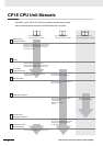
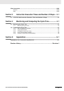
Manual Structure
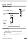
The following page structure and icons are used in this manual.
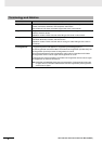
Special information in this manual is classified as follows:
Page Structure and Icons
Special Information
5 - 3
5 Installation and wiring
CP1E CPU Unit Hardware User’s Manual(W479)
5
5-2 Installation
5-2-1 Installation Location
DIN Track Installation
1
2
Release
DIN Track mounting pins
3
DIN Track
DIN Track mounting pins
Precautions for Correct Use
Tighten terminal block screws and cable screws to the following torques.
M4: 1.2 N·m
M3: 0.5 N·m
Use a screwdriver to pull down the DIN Track mounting pins from the back of the Units to release
them, and mount the Units to the DIN Track.
Fit the back of the Units onto the DIN Track by catching the top of the Units on the Track and then
pressing in at the bottom of the Units, as shown below.
Press in all of the DIN Track mounting pins to securely lock the Units in place.
5-2 Installation
5-2-1 Installation Location
Level 1 heading
Level 2 heading
Level 3 heading
Level 2 heading
Step in a procedure
Manual name
Special Information
(See below.)
Level 3 heading
Page tab
Gives the current
headings.
Indicates a step in a
procedure.
Gives the number
of the section.
This illustration is provided only as a sample and may not literally appear in this manual.
Icons are used to indicate
precautions and
additional information.
Precautions for Safe Use
Precautions on what to do and what not to do to ensure using the product safely.
Precautions for Correct Use
Precautions on what to do and what not to do to ensure proper operation and performance.
Additional Information
Additional information to increase understanding or make operation easier.
References to the location of more detailed or related information.