


IDL series User Guide
300
base ADSL2 depending upon the downstream rate. It is avaiable
only for ADSL2 Annex A.(length = 4 bytes)
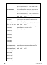
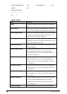
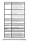
Max Nom PSD(dB/10)
This parameter specifies the maximum nominal transmit
PSD(MAXNOMPSD) level during initialization and showtime.
Value depends on CO MIB element settings and near end
transmitter capabilities and is exchanged in the G.994.1 Phase. It
is available only for ADSL2/ADSL2plus. Value ranges from -60 to
-40 in steps of 0.1 dBm/Hz.(length = 4 bytes)
Max Nom AtpPsd(dB/10)
This parameter specifies the maximum nominal aggregate
transmit power(MAXNOMATP) level during initialization and
showtime. Value depends on CO MIB element settings and local
capabilities and is exchanged in the G.994.1 Phase. It is available
only for ADSL2/ADSL2plus. Value ranges from 0 to 25.5 in steps
of 0.1 dBm.(length = 4 bytes)
DS PSD Mask
This configuration parameter defines that the downstream PSD
mask applicable at the U-C2 reference point. This MIB PSD mask
may impose PSD restrictions in addition to the Limit PSD mask
defined in the relevant Recommendation (e.g., G.992.5). (length =
4 bytes).
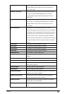
GsAnnexCOlToCxSwitch
Conexant parameter that is used to configure the switching point
between DBM-OL and XOL.(length = 4 bytes)
GsAnnexCSwitch
Conexant parameter that is used to configure the switching point
between Annex C and G.Span (IFM) and between Annex C and
G.Span Plus.(length = 4 bytes)
GsAnnexCToUqSwitch
Conexant parameter that is used to configure the switching point
between Annex C and G.Span Plus SUQ.(length = 4 bytes)
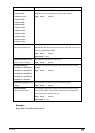
Min SnrMgnTime(sec)
This parameter indicates the time when the snr margin violation is
allowed. After this time expires and current snr is less than min
snr, the DSL line is dropped by the APIs.
Customer ID
This parameter indicates the customer ID.
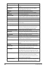
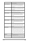
GsMPsdMaskType
Conexant parameter that selects the PSD mask option to be used
for Adsl2M.
GsSeltLoopGauge
This parameter should be set to the expected loop gauge.
Rate Ratio
This parameter specifies the latency rate for both channels in a
dual latency configuration. This parameter must be set the
parameter to a value greater than 0 and less than 100.
Target Snr Margin(dB/10)
Noise Margin the modem must achieve with a BER of 10 to the
power 7 or better to successfully complete initialization
Dnshift SnrMargin(dB/10)
Configured Signal/ Noise Margin for rate downshift. If the noise
margin falls below this level, the modem should attempt to