


2 – General Description
Chassis Controls and LEDs
2-2 59042-07 A
0
2.1
Chassis Controls and LEDs
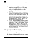
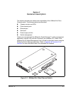
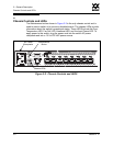
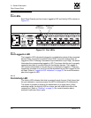
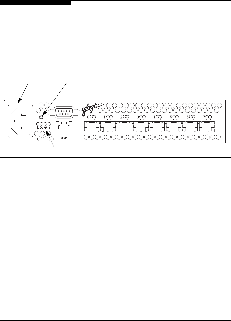
The Maintenance button shown in Figure 2-2 is the only chassis control and is
used to reset a switch or to recover a disabled switch. The chassis LEDs provide
information about the switch’s operational status. These LEDS include the Over
Temperature LED, Fan Fail LED, Heartbeat LED, and the Input Power LED. To
apply power to the switch, plug the power cord into the switch AC power
receptacle and into a 110 or 230 VAC power source.
Figure 2-2. Chassis Controls and LEDS
AC Power
Receptacle
Chassis LEDs
Maintenance
Button