


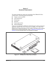
2 – General Description
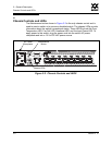
Chassis Controls and LEDs
2-4 59042-07 A
0
2.1.2
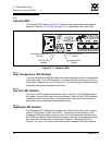
Chassis LEDs
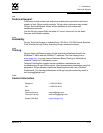
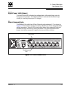
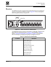
The chassis LEDs shown in Figure 2-3 provide status information about switch
operation. Refer to “Port LEDs” on page 2-6 for information about port LEDs.
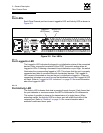
Figure 2-3. Chassis LEDs
2.1.2.1
Over Temperature LED (Amber)
The Over Temperature LED provides status information about the air temperature
inside the switch. This LED illuminates to indicate that the switch logic circuitry is
overheating. Refer to Section 5 Diagnostics/Troubleshooting for information about
troubleshooting over temperature conditions.
2.1.2.2
Fan Fail LED (Amber)
The Fan Fail LED indicates operational status of the fan. This LED illuminates if
the speed of the fan falls below the normal range. If the Fan Fail LED illuminates,
isolate the switch from the fabric, unplug the switch from the AC power source,
and contact your authorized maintenance provider.
2.1.2.3
Heartbeat LED (Amber)
The Heartbeat LED indicates the status of the internal switch processor and the
results of the Power On Self Test (POST). Following a normal power-up, the
Heartbeat LED blinks about once per second to indicate that the switch passed
the POST and that the internal switch processor is running. In maintenance mode,
the Heartbeat LED illuminates continuously. Refer to “Heartbeat LED Blink
Patterns” on page 5-2 for more information about Heartbeat LED blink patterns.
Over Temperature LED
(Amber)
Fan Fail LED
(Amber)
Heartbeat LED
(Amber)
Input Power LED
(Green)