


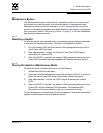
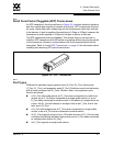

2 – General Description
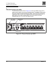
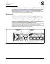
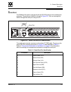
Chassis Controls and LEDs
59042-07 A 2-3
0
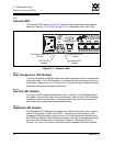
2.1.1
Maintenance Button
The Maintenance button is a dual-function momentary switch on the front panel.
Its purpose is to reset the switch or to place the switch in maintenance mode.
Maintenance mode sets the IP address to 10.0.0.1 and provides access to the
switch for maintenance purposes when flash memory or the resident configuration
file is corrupted. Refer to “Recovering a Switch” on page 5-11 for more information
about using maintenance mode.
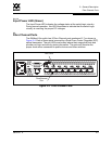
2.1.1.1
Resetting a Switch
To reset the switch, use a pointed tool to momentarily press and release (less than
2 seconds) the Maintenance button. The switch will respond as follows:
1. All of the chassis LEDs will illuminate and then extinguish leaving only the
Input Power LED illuminated.
2. After approximately 1 minute, the Power-On Self Test (POST) begins
illuminating all chassis LEDs.
3. When the POST is complete, the chassis LEDs extinguish leaving the Input
Power LED illuminated and the Heartbeat LED flashing once per second.
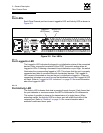
2.1.1.2
Placing the Switch in Maintenance Mode
To place the switch in maintenance mode, do the following:
1. Isolate the switch from the fabric.
2. Press and hold the Maintenance button with a pointed tool for 2–4 seconds.
When the Input Power LED alone is illuminated, release the button.
3. After approximately 1 minute, the POST begins illuminating all chassis
LEDs.
4. When the POST is complete, the chassis LEDs extinguish leaving the Input
Power LED and the Heartbeat LED illuminated. The Heartbeat LED
illuminates continuously while the switch is in maintenance mode.
To exit maintenance mode and return to normal operation, momentarily press and
release the Maintenance button to reset the switch.