2 – General Description
Chassis Controls and LEDs
2-2 59021-08 B
D
2.1
Chassis Controls and LEDs
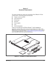
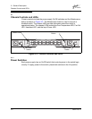
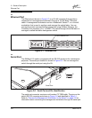
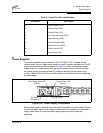
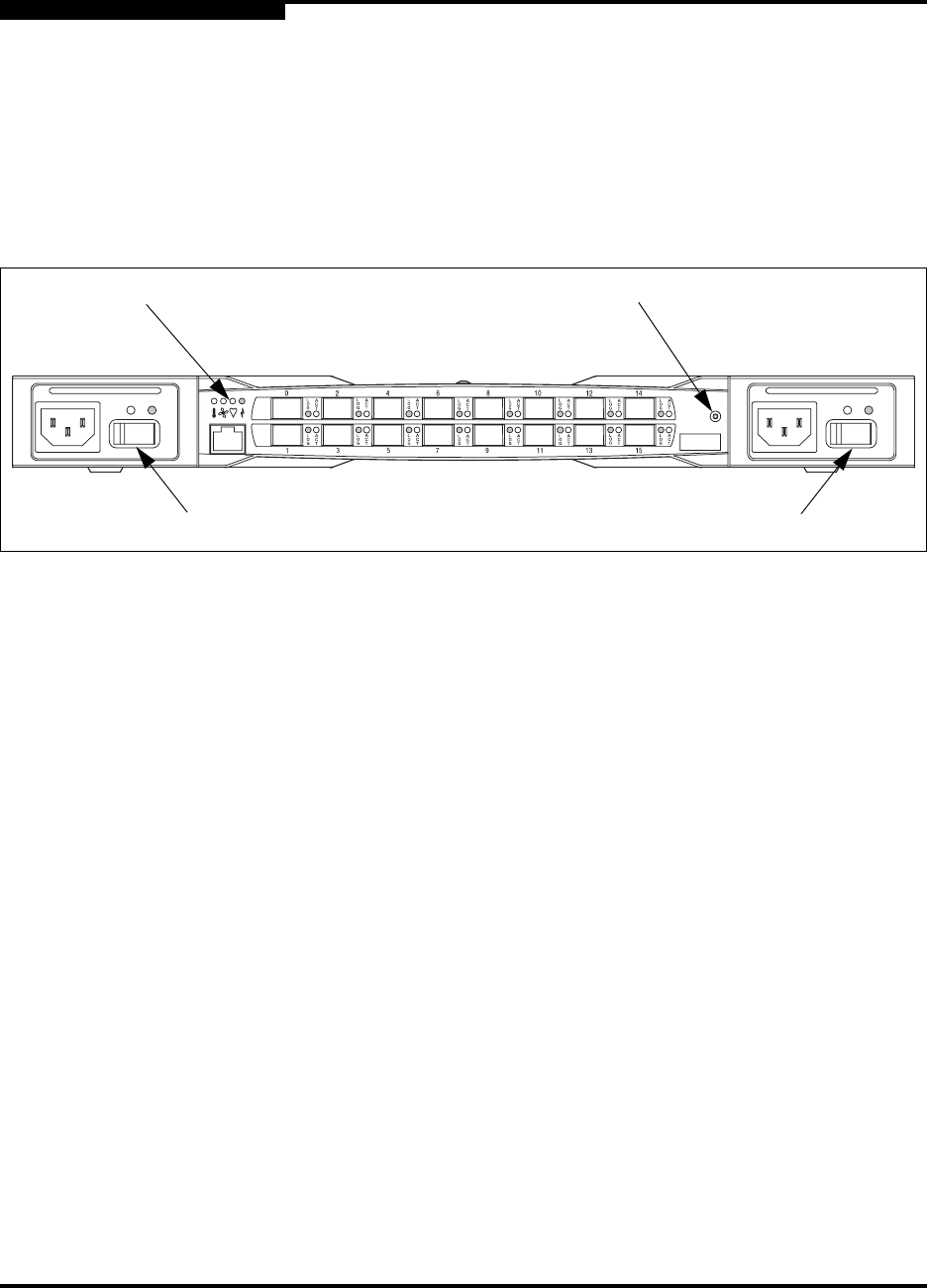
Chassis controls include the power supply On/Off switches and the Maintenance
button as shown in Figure 2-2. The Maintenance button is used to recover a
disabled switch. The chassis LEDs provide information about the switch’s
operational status. The chassis LEDs include the Over Temperature LED, Fan Fail
LED, Heartbeat LED, and the Input Power LED.
Figure 2-2. Chassis Controls and LEDS
2.1.1
Power Switches
Each power supply has an On/Off switch that controls power to the switch logic
circuitry. To apply power to the switch, place both switches in the On position.
Chassis LEDs
Left Power
Switch
Right Power
Switch
Maintenance
Button


