


2 – General Description
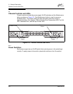
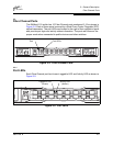
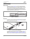
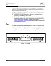
Chassis Controls and LEDs
2-4 59021-08 B
D
2.1.3.1
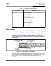
Over Temperature LED (Amber)
The Over Temperature LED provides status information about the air temperature
inside the switch. This LED illuminates to indicate that the switch logic circuitry is
overheating. Refer to Section 5 Diagnostics/Troubleshooting for information about
troubleshooting over temperature conditions.
2.1.3.2
Fan Fail LED (Amber)
The Fan Fail LED indicates operational status of all fans. This LED illuminates if
the speed of any fan falls below the normal range. Removing a fan will not
illuminate the Fan Fail LED. Refer to Section 5 Diagnostics/Troubleshooting for
information about troubleshooting fan failure conditions.
2.1.3.3
Heartbeat LED (Amber)
The Heartbeat LED indicates the status of the internal switch processor and the
results of the Power On Self Test (POST). Following a normal power-up, the
Heartbeat LED blinks about once per second to indicate that the switch passed
the POST and that the internal switch processor is running. In maintenance mode,
the Heartbeat LED illuminates continuously. Refer to ”Heartbeat LED Blink
Patterns” on page 5-2 for more information about Heartbeat LED blink patterns.
2.1.3.4
Input Power LED (Green)
The Input Power LED indicates the voltage status at the switch logic circuitry.
During normal operation, this LED illuminates to indicate that the switch logic
circuitry is receiving the proper DC voltages.