


Rev.1.10 Jul 01, 2005 page 97 of 318
REJ09B0124-0110
M16C/6N Group (M16C/6NK, M16C/6NM) 12. Timers
Under development
This document is under development and its contents are subject to change.
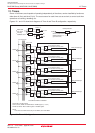
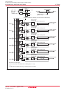
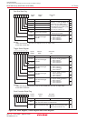
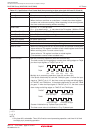
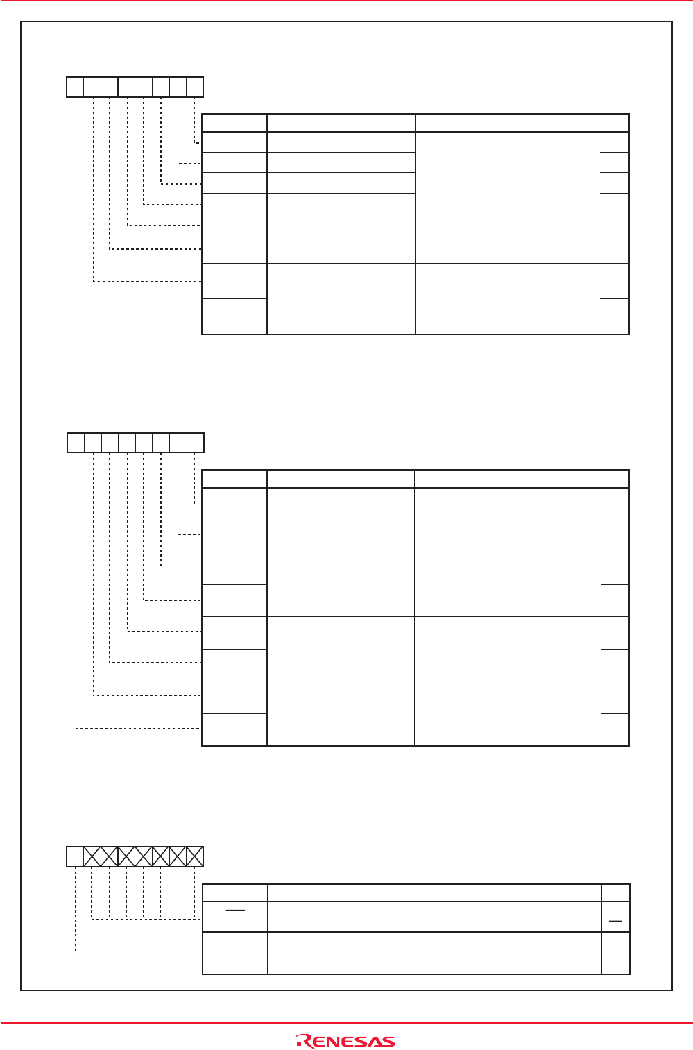
Figure 12.6 ONSF Register, TRGSR Register and CPSRF Register
One-Shot Start Flag
Symbol Address
ONSF 0382h
Timer A0 One-Shot Start Flag
Timer A1 One-Shot Start Flag
Timer A2 One-Shot Start Flag
Timer A3 One-Shot Start Flag
Timer A4 One-Shot Start Flag
Bit Name FunctionBit Symbol
b7 b6 b5 b4 b3 b2 b1 b0
0 0 : Input on TA0IN is selected
(1)
0 1 : TB2 is selected
(2)
1 0 : TA4 is selected
(2)
1 1 : TA1 is selected
(2)
Timer A0 Event/Trigger
Select Bit
b7 b6
RW
The timer starts counting by setting
this bit to "1" while the TMOD1 to
TMOD0 bits in the TAiMR register (i =
0 to 4) = 10b (one-shot timer mode)
and the MR2 bit in the TAiMR register
= 0 (TAiOS bit enabled).
When read, its content is "0".
Z-phase Input Enable Bit
0 : Z-phase input disabled
1 : Z-phase input enabled
RW
RW
RW
RW
RW
RW
RW
RW
NOTES:
1.Make sure the PD7_1 bit in the PD7 register is set to "0" (input mode).
2.Over flow or under flow.
TA1OS
TA2OS
TA0OS
TA3OS
TA4OS
TA0TGL
TA0TGH
TAZIE
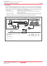
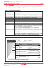
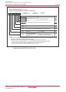
Symbol Address After Reset
TRGSR 0383h 00h
Timer A1 Event/Trigger
Select Bit
Trigger Select Register
Bit Name FunctionBit Symbol
b7 b6 b5 b4 b3 b2 b1 b0
Timer A2 Event/Trigger
Select Bit
Timer A3 Event/Trigger
Select Bit
Timer A4 Event/Trigger
Select Bit
b1 b0
b3 b2
b5 b4
b7 b6
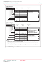
NOTES:
1.Make sure the port direction bits for the TA1IN to TA4IN pins are set to "0" (input mode).
2.Over flow or under flow.
0 0 : Input on TA1IN is selected
(1)
0 1 : TB2 is selected
(2)
1 0 : TA0 is selected
(2)
1 1 : TA2 is selected
(2)
0 0 : Input on TA2IN is selected
(1)
0 1 : TB2 is selected
(2)
1 0 : TA1 is selected
(2)
1 1 : TA3 is selected
(2)
0 0 : Input on TA3IN is selected
(1)
0 1 : TB2 is selected
(2)
1 0 : TA2 is selected
(2)
1 1 : TA4 is selected
(2)
0 0 : Input on TA4IN is selected
(1)
0 1 : TB2 is selected
(2)
1 0 : TA3 is selected
(2)
1 1 : TA0 is selected
(2)
RW
RW
RW
RW
RW
RW
RW
RW
RW
TA1TGL
TA1TGH
TA2TGL
TA2TGH
TA3TGL
TA3TGH
TA4TGL
TA4TGH
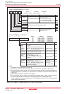
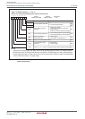
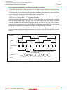
After Reset
00h
Symbol
CPSRF
Clock Prescaler Reset Flag
Bit Name FunctionBit Symbol
b7 b6 b5 b4 b3 b2 b1 b0
RW
RW
(b6-b0)
Setting this bit to "1" initializes the
prescaler for the timekeeping clock.
(When read, its content is "0".)
Nothing is assigned. When write, set to "0".
When read, their contents are indeterminate.
CPSR Clock Prescaler Reset Flag
Address After Reset
0381h 0XXXXXXXb