


Rev.1.10 Jul 01, 2005 page 65 of 318
REJ09B0124-0110
M16C/6N Group (M16C/6NK, M16C/6NM) 9. Interrupt
Under development
This document is under development and its contents are subject to change.
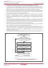
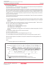
9.5 Interrupt Control
The following describes how to enable/disable the maskable interrupts, and how to set the priority in which
order they are accepted. What is explained here does not apply to non-maskable interrupts.
Use the I flag in the FLG register, IPL, and the ILVL2 to ILVL0 bits in the each interrupt control register to
enable/disable the maskable interrupts. Whether an interrupt is requested is indicated by the IR bit in the
each interrupt control register.
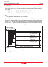
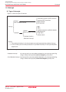
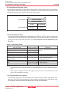
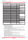
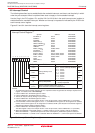
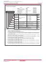
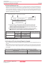
Figures 9.3 and 9.4 show the interrupt control registers.
Figure 9.3 Interrupt Control Registers (1)
0041h
0042h
0043h
0045h
0046h
0047h
004Ah
004Bh, 004Ch
004Dh
004Eh
0051h, 0053h, 004Fh
0052h, 0054h, 0050h
0055h, 0056h
0059h
005Ah
005Ch
Interrupt Control Register
(1)
C01WKIC
(8)
C0RECIC
C0TRMIC
TB5IC/S5IC
(5)
TB4IC/U1BCNIC
(2)
TB3IC/U0BCNIC
(3)
U2BCNIC
DM0IC, DM1IC
C01ERRIC
(6) (9)
ADIC/KUPIC
(6)
S0TIC to S2TIC
S0RIC to S2RIC
TA0IC, TA1IC
TA4IC
TB0IC/S6IC
(7)
TB2IC
XXXXX000b
XXXXX000b
XXXXX000b
XXXXX000b
XXXXX000b
XXXXX000b
XXXXX000b
XXXXX000b
XXXXX000b
XXXXX000b
XXXXX000b
XXXXX000b
XXXXX000b
XXXXX000b
XXXXX000b
XXXXX000b
NOTES:
1. To rewrite the interrupt control registers, do so at a point that does not generate the interrupt request for that
register. For details, refer to 22.7 Interrupt.
2. Use the IFSR07 bit in the IFSR0 register to select.
3. Use the IFSR06 bit in the IFSR0 register to select.
4. This bit can only be reset by writing "0" (Do not write "1").
5. Use the IFSR04 bit in the IFSR0 register to select.
The S5IC register is only in the 128-pin version. In the 100-pin version, set the IFSR04 bit to "0" (Timer B5).
6. If the PCLK6 bit in the PCLKR register is set to "1", C01ERRIC/KUPIC register can be assigned in an address
004Dh, and the ADIC register can be assigned in an address 004Eh. (SFR location of the KUPIC register is
changed from address 004Eh to address 004Dh.)
7. Use the IFSR05 bit in the IFSR0 register to select.
The S6IC register is only in the 128-pin version. In the 100-pin version, set the IFSR05 bit to "0" (Timer B0).
8. When the IFSR02 bit in the IFSR0 register = 0 (CAN0/1 wake-up or error), CAN0/1 wake-up is selected.
When the IFSR02 bit = 1 (CAN0 wake-up/error or CAN1 wake-up/error), CAN0 wake-up/error is selected.
9. When the IFSR02 bit = 0, CAN0/1 error is selected. When the IFSR02 bit = 1, CAN1 wake-up/error is selected.
b2 b1 b0
0 0 0 : Level 0 (interrupt disabled)
0 0 1 : Level 1
0 1 0 : Level 2
0 1 1 : Level 3
1 0 0 : Level 4
1 0 1 : Level 5
1 1 0 : Level 6
1 1 1 : Level 7
0 : Interrupt not requested
1 : Interrupt requested
Noting is assigned. When write, set to "0".
When read, their contents are indeterminate.
RW
RW
RW
RW
(4)
-
Interrupt Request Bit
Interrupt Priority Level
Select Bit
Bit Name FunctionBit Symbol
RW
ILVL0
IR
ILVL1
ILVL2
-
(b7-b4)
Symbol Address After Reset
b7 b6 b5 b4 b3 b2 b1 b0