


Rev.1.10 Jul 01, 2005 page 238 of 318
REJ09B0124-0110
M16C/6N Group (M16C/6NK, M16C/6NM) 20. Flash Memory Version
Under development
This document is under development and its contents are subject to change.
20. Flash Memory Version
Aside from the built-in flash memory, the flash memory version microcomputer has the same functions as the
masked ROM version.
In the flash memory version, the flash memory can perform in four rewrite mode: CPU rewrite mode, standard
serial I/O mode, parallel I/O mode and CAN I/O mode.
Table 20.1 lists the specifications of the flash memory version. See Tables 1.1 and 1.2 Performance
outline, for the items not listed in Table 20.1). Table 20.2 shows the outline of flash memory rewrite mode.
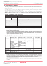
Table 20.1 Flash Memory Version Specifications
Item Specifications
Flash Memory Operating Mode 4 modes (CPU rewrite, standard serial I/O, parallel I/O, CAN I/O)
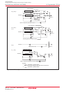
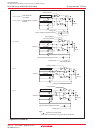
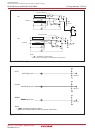
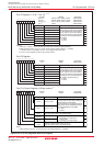
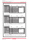
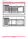
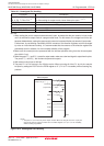
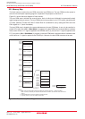
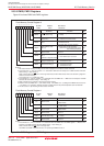
Erase Block User ROM Area See Figure 20.1 Flash Memory Block Diagram
Boot ROM Area 1 block (4 Kbytes)
(1)
Program Method In units of word, in units of byte
(2)
Erase Method Collective erase, block erase
Program and Erase Control Method Program and erase controlled by software command
Protect Method Lock bit protects each block
Number of Commands 8 commands
Program and Erase Endurance
(3)
100 times
ROM Code Protection Parallel I/O , standard serial I/O and CAN I/O modes are supported.
NOTES:
1. The boot ROM area contains a standard serial I/O mode and CAN I/O mode rewrite control program which is stored in
it when shipped from the factory. This area can only be rewritten in parallel I/O mode.
2. Can be programmed in byte units in only parallel I/O mode.
3. Definition of program and erase endurance
The programming and erasure times are defined to be per-block erasure times. For example, assume a case where a 4K-byte
block A is programmed in 2,048 operations by writing one word at a time and erased thereafter. In this case, the block is
reckoned as having been programmed and erased once.
If a product is guaranteed of 100 times of programming and erasure, each block in it can be erased up to 100 times.
Table 20.2 Flash Memory Rewrite Modes Overview
Flash Memory
CPU Rewrite Mode
(1)
Standard Serial I/O Mode
Parallel I/O Mode CAN I/O Mode
Rewrite Mode
Function
Areas which User ROM area User ROM area User ROM area User ROM area
can be Rewritten
Boot ROM area
Operation Single-chip mode Boot mode Parallel I/O mode Boot mode
Mode Boot mode (EW0 mode)
ROM Programmer
None Serial programmer Parallel programmer CAN programmer
The user ROM area is
rewritten when the CPU
executes software
commands.
EW0 mode:
Rewrite in areas other
than flash memory
(2)
EW1 mode:
Can be rewritten in the
flash memory
The user ROM area is
rewritten using a
dedicated serial
programmer.
Standard serial I/O mode 1:
Clock synchronous
serial I/O
Standard serial I/O mode 2:
UART
(3)
The boot ROM and user
ROM areas are rewritten
using a dedicated parallel
programmer.
The user ROM area is
rewritten busing a dedicated
CAN programmer.
NOTES:
1. The PM13 bit remains set to “1” while the FMR01 bit in the FMR0 register = 1 (CPU rewrite mode enabled). The PM13 bit
is reverted to its original value by setting the FMR01 bit to “0” (CPU rewrite mode disabled). However, if the PM13 bit is
changed during CPU rewrite mode, its changed value is not reflected until after the FMR01 bit is set to “0”.
2. When in CPU rewrite mode, the PM10 and PM13 bits in the PM1 register are set to “1”. The rewrite control program can
only be executed in the internal RAM area.
3. When using the standard serial I/O mode 2, make sure a main clock input oscillation frequency is set to 5 MHz, 10 MHz
or 16 MHz.