


Unit 6: Maintenance
SATO HT200e Operator Manual PN 9001103B Page 6-8
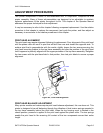
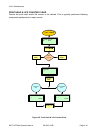
DISPENSER SENSOR ADJUSTMENT
The dispenser sensor is comprised of two parts; the transmitter and the reciever. The
transmission and reception of the dispenser sensor may be electrically adjusted through a
potentiometer integrated into the main circuit board. This potentiometer is externally accessible,
thusly dismantling of the printer is not required.
For proper performance, the sensor must have both a low-level and a high-level voltage reading.
The low-level voltage must not be greater than 0.4V and the high-level voltage must not be less
than 2.0V. If the following procedure cannot achieve the required voltage, replace the two
components in accordance with their relative procedures located within the Replacement
Procedures unit of this manual. If all else fails, the main circuit board will have to be replaced.
This adjustment procedure will require the use of a multimeter and the SATO Test Module. The
voltage level may also be checked by connecting the multimeter probes directly to the CH1a (-)
and the CH2b (+) pins of the test terminal and following steps 6 through 12 of the procedure
below.
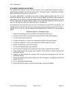
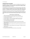
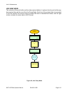
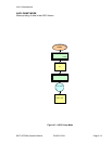
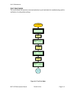
Reference Figure 6-3, Test Module Usage
1 Remove the maintenance cover located on the right side of the printer.
2 Connect the test module to the terminal located to the left of the potentiometers.
3 Turn test module dial to position 4.
4 Connect the positive (+) probe of the multimeter to pin SIG on the test module.
5 Connect the negative (-) probe of the multimeter to GRD on the test module.
6 Ensure the multimeter is set for DC reading.
7 Turn the VR4 potentiometer fully clockwise.
8 Press and hold the [9] key while switching on the printer to enter the Service Mode.
9 Place a label without the eye-mark part in position to be read by the sensor and note the
multimeter reading.
10 Replace the label without the eye-mark with one that has the eye-mark and note the
multimeter reading.
11 Subtract the previous multimeter reading from the last reading. The difference should be
greater than 0.9V.
12 Set the difference to the maximum.
13 Disconnect the test module, load printer with media, and test print labels.