


Using the Modbus Plus Ports
174
870 USE 101 00 V.3
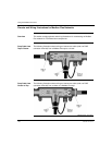
Modbus Plus Addresses
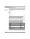
Introduction Modbus Plus devices function as peers on a logical ring. Each device accesses the
network by acquiring a token frame that is passed in a rotating address sequence.
Each device on a Modbus Plus network needs a unique address in the range
1...64. The device address determines the logical order in which the network token
will be passed from device to device.
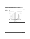
Address
Sequence
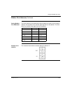
The assignment of addresses does not have to map to the physical layout of the
network–e.g., device 17 is placed physically before device 3. This is important to
understand because the network's token rotation is defined by device addresses-
e.g., device 2 will pass the token to device 3, device 3 to device 4, etc.
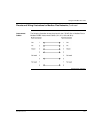
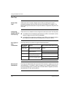
Illegal Addresses If you set the node address to 00 or to a value greater than 64:
● The COM LED will go ON steadily to indicate an illegal address assignment.
● The Run LED will flash 4 times.
● The Processor Adapter will not run until you set a valid, unused address on the
Option Adapter and cycle power.
Continued on next page
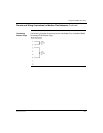
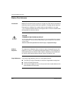
CAUTION
COMMUNICATION ERRORS MAY RESULT
Do not install a Modbus Plus Option Adapter before you have set its Modbus Plus address
for your application. See your network administrator to get the Modbus Plus node address
for this module.
Failure to observe this precaution can result in injury or equipment damage.