


Using Peer Cop with Concept
870 USE 101 00 V.3 371
Defining the References for the Next Node, Continued
Defining Global
Inputs
Follow the steps in the table below to define the global input data from the
supervisory PLC at Modbus Plus address 1.
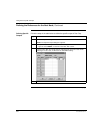
Next Step Defining references for the supervisory PLC.
Step Action
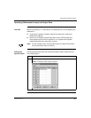
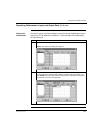
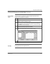
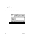
1 Click on the Global Input... button.
Result: The Global Input dialog box appears.
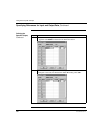
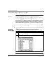
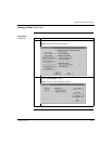
2 Since this device will be receiving data from the CPU at address 1, you do not
need to change the default sending address (selected under the heading 1-64).
Type 400001 in the Dest. Ref column on the first line, to indicate the first register
the CPU will use to store the input data.
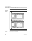
3 Type the value 4 in the Index column, indicating that the CPU will receive part of
the global input data beginning with the fourth word.
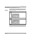
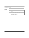
4 Type the value 7 in the Length column, indicating that the CPU will accept seven
words of the global input data. Leave the default
BIN setting.
5 Click <OK>.