


I/O Mapping an I/OBus Network with Modsoft
228
870 USE 101 00 V.3
Editing the I/OBus I/O Map
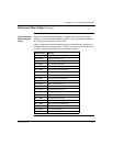
Overview The maximum number of modules which can be I/O Mapped on the I/OBus
network depends on your Processor Adapter:
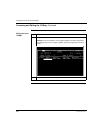
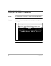
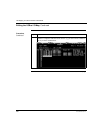
You may use up to 16 IOBUS screens to map your I/OBus network. Each page
allows you to enter up to 16 I/O base and/or InterBus I/O modules.
The first column on the screen tells you which page you are on.
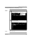
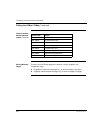
Procedure To enter I/O bases or Interbus I/O modules in the I/OBus I/O Map, perform the
steps in the following table.
Continued on next page
Processor Adapter Max. Modules Max. I/O Bits
171 CCS 760 00 128 2048
171 CCC 760 10 256 4096
Step Action
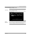
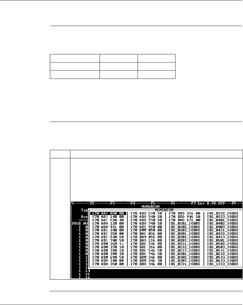
1 Place the cursor in the Module column in row 1 (for NODE 01) and push the <F8>
key OR <Shift> <?>.
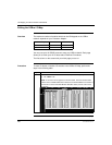
Result:
A list of I/O names appears, as shown below. This list includes model
numbers for the available Momentum I/O bases and Terminal Block I/O modules. It
also includes a series of InterBus Module Identifier codes (see list at the end of
this section).