


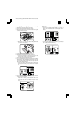
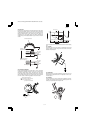
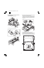
(2) Manual paper feed tray operation
Select the manual paper feed tray and press the START button, and
the manual paper feed roller will be turned on to bring the paper feed
roller in contact with paper and lift the shutter simultaneously.
The drive power of the main motor is transmitted through the manual
paper feed roller clutch to the manual paper feed roller, rotating the
manual paper feed roller and feeding paper.
(3) Resist roller
In order to make synchronization between the paper lead edge fed
from the paper feed port and the image lead edge, the roller is kept
stationary for a certain time after the paper reaches at the roller to
warp the paper a little.
When the paper is warped to a certain level, the resist roller solenoid
is turned on to release the resist roller clutch.
The drive power of the main motor is transmitted through the resist
roller clutch to the resist roller, rotating the resist roller and feeding
paper.
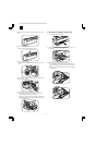
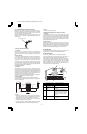
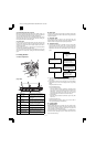
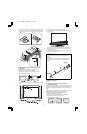
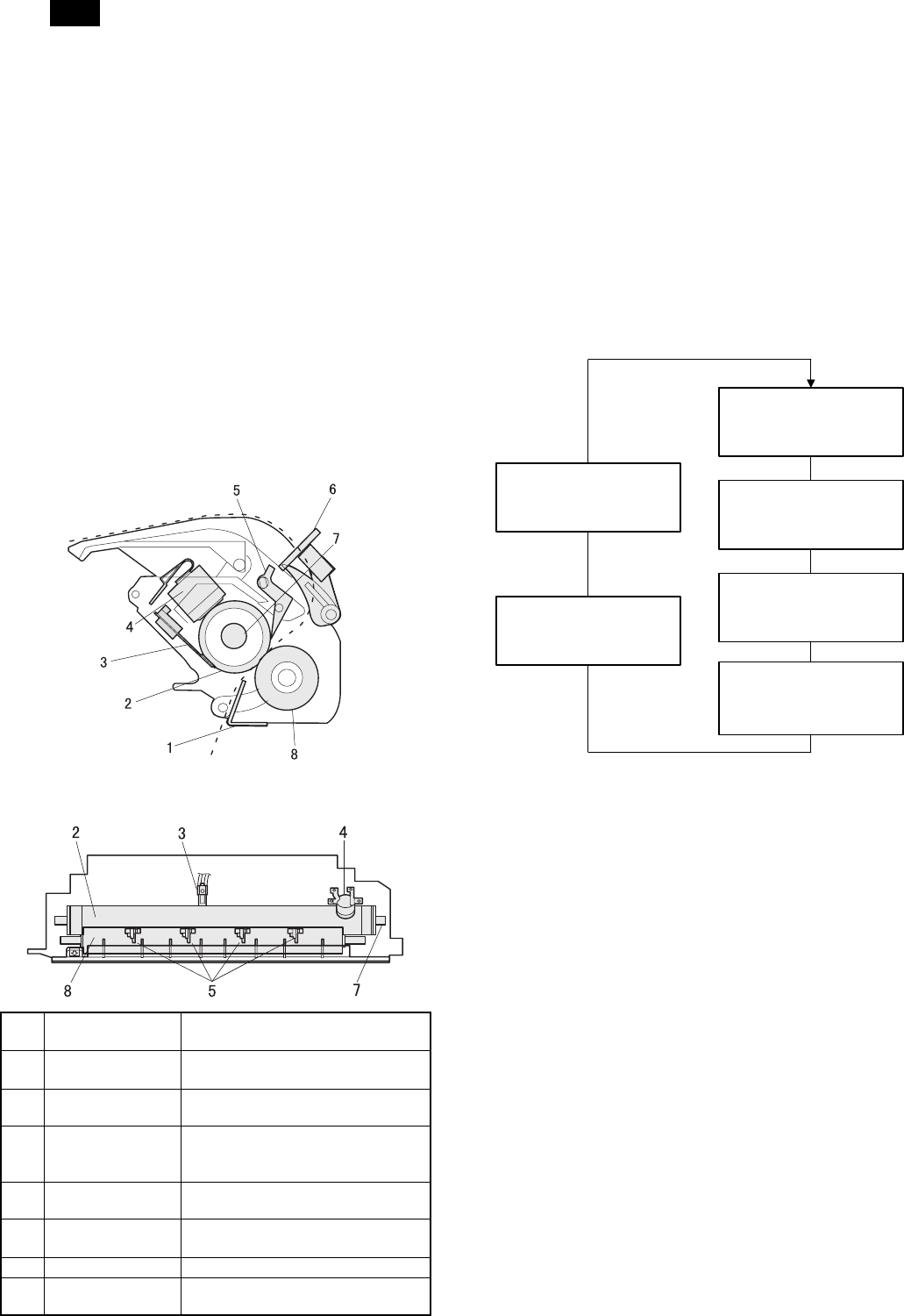
6. Fusing section
A. Basic composition
(Top view)
1 Before-fusing
paper guide
Guides the paper transported from
the process section to the fusing unit.
2 Upper heat roller Applies heat and pressure to the
paper to fuse.
3 Thermistor Detects the surface temperature of
the upper heat roller.
4 Thermostat Stops power supply to the heat roller
in case of an abnormally high
temperature of the heat roller.
5 Separation pawl Separates the print paper from the
upper heat roller.
6 POD1 Detects that the paper has been
transported from the fusing section.
7 Heater lamp Heats the heat roller.
8 Lower heat roller Applies a pressure to the paper
together with the upper heat roller.
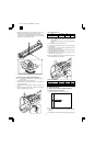
B. Heat roller
A pressure roller is used for the heat roller and a silicone rubber roller
is used for the lower heat roller for better toner fusing performance
and paper separation.
C. Separator pawl
Four separator pawls are used on the upper heat roller. The
separator pawls are teflon coated to reduce friction with the roller and
prevent a smear on the paper caused by the separator pawl.
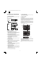
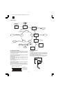
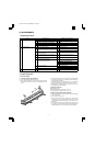
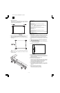
D. Thermal control
1) The heater lamp, thermistor, main PWB, DC power supply PWB,
and triac within the power supply unit are used to control the
temperature in the fuser unit.To prevent against abnormally high
temperature in the fuser unit, a thermostat is used for safety pur-
poses.
2) The surface temperature of the upper heat roller is set to 180˚C ~
195˚C. The surface temperature during the power save mode is
set to 100˚C.
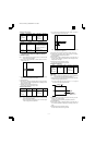
3) The self-check function comes active when one of the following
malfunctions occurs, and an "H" is displayed on the copy quantity
display.
Fusing temperature error value
H4 (Low temperature error)
• During machine operation
The case where the fusing temperature (thermistor output
value) does not reach 155˚C within 55 sec from lighting of the
heater lamp. (If the toner motor rotates for 10 sec or more
continuously when starting the machine, the case where the
fusing temperature does not reach 155˚C within 60 sec.)
• During printing
When the fusing temperature (thermistor output value) falls
below 145˚C.
H3 (High temperature error)
Fusing temperature (thermistor output value) of about 220 to
240˚C (varies depending on the resistance.)
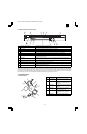
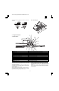
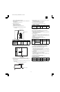
E. Fusing resistor
(1) Fusing resistor
Since the upper heat roller is conductive when copy paper is highly
moistured and the distance between the transfer unit and the fusing
unit is short, the transfer current leaks through the copy paper, the
upper heat roller and the discharging brush.
To prevent against this, a resistor of 150MOhm is provided between
the frame and the discharge brush to minimize leak current and
improve transfer efficiency.
Safety device
(thermal breaker, thermal
fuse)
Triac (in the
power supply unit)
Heated by the
heater lamp.
(950W )
The surface temperature
of the upper heat roller
is sensed by the thermistor.
Level of the thermistor is
controlled by the main PWB.
With the signal from the
main PWB, the triac is
controlled on and off.
(power supply PWB )
AR-160/161 FM/E [6] OPERATIONAL DESCRIPTIONS 11/27/1998
AR-161
6 – 7