


SVP 450 PLUS - SVD 500 PLUS
18
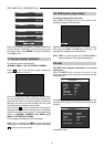
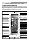
SCREEN SIZE D
Useful area 4/3
Diagonal Width Height
(Inches) (cm.) (cm.) (cm.)
60” 121,9 91,4 204
80” 165,5 124,9 263
90” 182,9 137,2 283
100” 203,2 152,4 322
120” 243,8 182,9 383
150” 304,8 228,6 473
180” 365,7 274,3 563
200” 406,4 304,8 618
250” 508,0 381,0 768
300” 609,6 457,2 918
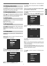
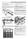
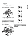
FRONT
H
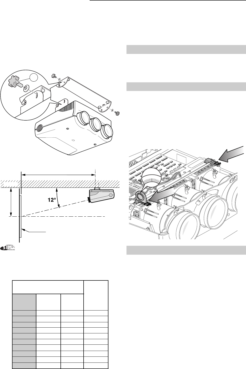
5- Turn the projector upside down and hang on the ceiling
with the assembly brackets.
6- Tilt the projector to centre the vertical picture and screw
the two securing screws (H)
Note: Insert the special curved washers between the
ceiling bracket and the securing screws. For a correct
installation the concave surface of the washer should be
towards the bracket. For safety purposes, use only the
assembly kit supplied.
Note: the tilting angle between the base plane of the
projector and the lenses’ axis should be 12°.
Multimedia S.P.A. declines all responsibility for
damages to persons or things caused by incorrect or
careless installation which must be effected by a qualified
technician.
TABLE 3: CEILING FRONT PROJECTION.
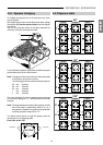
45
0
9
0
90
4
5
12°
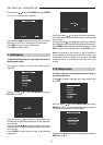
4.5 Spacers
The projector uses some spacers for the “Scheimpflug”
correction of the lenses’ angle so as to achieve a perfect
focusing uniformity over the entire screen surface.
The projector is factory set with spacers for a ceiling front
installation with a 90” screen diagonal.
The projector is equipped with a complete set of optional
spacers for screens ranging from 60” up to 300”.
The spacers are mounted between the lenses and the
assembling block surface where they are fixed with 4
screws.
More than one spacer might be needed to achieve proper
adjustment.
Lorrect use
of the spacers
, as shown in the tables, is of
paramount importance for perfect focus uniformity.
E
D
SCREEN CENTRE
SCREEN
WALL
D = Distance between the line of the first hole of the
assembly bracket and the screen.
Note:
The screen size refers to the useful area (4/3
format).
4.3.5 Ceiling rear projection
Rear projection installation is done by hanging the
projector on the ceiling and following the instructions given
for front installation.
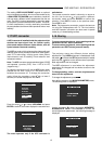
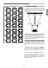
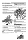
4.4 Projection angle measurement
Use a goniometer to determine the projection angle. First
of all, remove the projector’s top cover and then use the
surface shown in the figure as reference for the
goniometer.
The reference surface has an angle of 12 degrees
compared to the projector’s base when it is perfectly level.