


SVP 450 PLUS - SVD 500 PLUS
19
ENGLISHENGLISH
ENGLISHENGLISH
ENGLISH
A
B
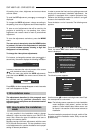
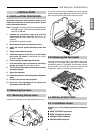
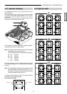
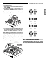
4.5.1. Spacers changing
To change the spacers first of all remove the top cover
and front panel.
Now slightly loosen the 4 screws (A) for each tube, change
the spacers (B) (see the spacers table) and then tighten
the screws.
You can only see two screws in the figure because the
other two are under the projection tube.
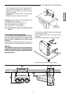
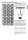
For the different installation types there are different spacer
combinations that have to be mounted.
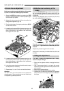
Note: The spacers have their thickness value expressed
in millimetres and printed on them.
The following pieces are included with the projector:
0,2 mm: 6 pieces
0,3 mm: 6 pieces
0,5 mm: 4 pieces
1 mm: 6 pieces
2 mm: 4 pieces
The 1mm (6 pieces), 0.3 mm (4 pieces) spacers are used
for the factory setting (90” 14°), while the others are inside
the pack.
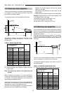
Note: The angle between the base of the projector and the
axis of the tubes is mechanically fixed at 12°; so, if
the projector is installed on a perfectly horizontal table
or ceiling, projection angle will be 12°.
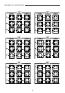
The figure shows where to install the spacers with the
values given in the following table.
Front view of the CRT.
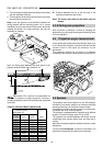
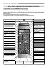
4.5.2 Spacers table
CRT LENS
SPACERS SPACERS
1
0,2
0,5
2
0,3
0 0,3
0,3
1
0,2
0,5
1
0,2
0,5
00
2
0,3
1
0,2
0,5
0,3
0,3
0
1
0,5
0,5
1
0,5
0,5
2
0,2
0,5
0 0,3
0,3
22
00
2
0,2
0,5
0,3
0,3
0
1
0,2
1
0,2
2
1
0 0,3
0,3
2
0,3
2
0,3
00
2
1
1
0,2
1
0,2
0,3
0,3
0
60"
GREENBLUE RED
11
0,3
0 0,3
11
00
1
0,3
1
0,3 0
1
0,3
1
0,3
1
0,3
1
0,5
0,2
1
0,5
0,2
0 0,3
00
1
0,3
0,3 0
1
0,3
0,3
0 0,3
1
00
1
0,5
0,2
0,5
0,2
1
0,5
0,2
0,2
1
0,5
0,2
0,2
1
0,3
0,3
0,3 0
100"
GREENBLUE RED
1
0,3
1
0,5
0,2
0 0,5
1
0,3
1
0,3
00
1
0,5
0,3
1
0,3
0,5 0
1
0,3
0,3
1
0,5
0,2
1
0,5
0,2
2
0 0,5
00
21
0,3
0,3
0,5 0
1
1
2
0,3
0,2
0 0,5
22
00
2
0,3
0,2
1
1
0,5 0
80"
GREENBLUE RED