


SVP 450 PLUS - SVD 500 PLUS
7
ENGLISHENGLISH
ENGLISHENGLISH
ENGLISH
••
••
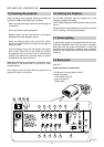
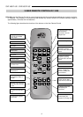
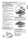
• THE FOLLOWING FUNCTIONS ARE ON THE
PANEL:
1- Power switch.
2- Fuse holder. The fuse type is 5A, T delayed.
Attention:
For continued protection against the risk of fire,
replace only with one of the same type and rating.
3- Mains power connector. To connect the power cable
90-270Vac 48-62Hz
4- Video output: CVBS.
5- Video 2: CVBS: (Signal input).
6- Video 1: CVBS: (Signal input).
7- S-VHS: (Signal input).
8- Connector SCART: (Input/output).
9- Red BNC input (RGB input) or Cr (components
input).
10- Green BNC input (RGB input) or Y (components
input).
11- Blue BNC input (RGB input) or Cb (components
input).
12- Sync H or H-V. Horizontal synchro or composite
synchro.
13- Sync V. Vertical synchronism
14- RS422 connector. To connect and control the
projector from a PC..
15- +12V connector (output). It has a +12V output when
the projector is on. This output can activate a relay
with a current less than 10mA. (for example, to enable
a circuit for the automatic unwinding and rewinding
of the motorised screen).
16- Screen command. It has +12V in output when the
aspect ratio selected with the button is SMALL.
It is used to change screen dimensions automatically.
17- Remote control cable input. To connect the RC3000
remote control cable.
18- VGA-SVGA signals input DB 15 connector
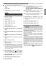
19- Rear panel buttons:
Picture adjustment. Each time you press a button
you select one of the follow controls:
Contrast, Brightness, Colour-Hue, Peaking.
Use
the + and - buttons to modify the value of the
selected control.
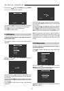
INFO Press this button to have the current projector
settings (ref. INFORMATION paragraph)
To modify the input selection sequentially; it starts
the projector from the STAND-BY state.
20- Led pilot light. (Red = STAND-BY), (Green = ON).
21- LED, blinks (red) when signal from the remote control
is received.
22- Remote control signal receiver (rear).
23- Remote control signal receiver (front).
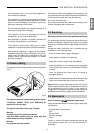
2.9 Cathode-ray tube phosphor
burning
One of the possible causes for burning could be when a
static image of a computer or video recorder signal is
projected for more than an hour.
The static image remains impressed on the screen even
when the signal changes.
Whenever it is necessary to visualise a static image for
more than one hour lower the contrast as much as possible
(CONTR key).
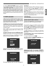
The same problem arises when visualising an image in a
different format for a long time. The smaller picture could
remain impressed on the screen (for instance, visualising
a 16:9 image on a 4:3 screen or vice versa). In this case
we suggest reducing the contrast of the small picture as
much as possible. These measures will reduce the risk of
CRT phosphor burning. If possible, always use the same
picture size.
Read the warranty enclosed with the product and
consult your dealer or qualified personnel.