


SVP 450 PLUS - SVD 500 PLUS
23
ENGLISHENGLISH
ENGLISHENGLISH
ENGLISH
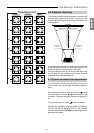
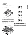
9. Use the yoke rings (centering magnets A and B) to
shift the green tube image onthe centre of the screen
reference point. Repeat the procedure for each tube.
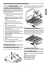
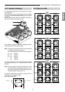
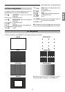
4.11 Setting of deflection connectors
Looking at the projector from the back panel, on the
right side near the blue tube, there are 3 connectors
for horizontal deflection and 3 more for vertical
deflection, see following figure.
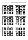
The setting of the deflection connectors must be carried
out as in the
following pictures:
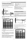
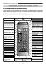
B
A
RED
GREEN
BLUE
R
G
B
RED WIRE YELLOW WIRE
BLUE WIRE
GREEN WIRE
FRONT DESKTOP PROJECTION
HORIZONTAL
DEFLECTION
CONNECTORS
VERTICAL
DEFLECTION
CONNECTORS
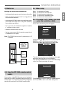
6. Turn on the projector.
7. Select the type of installation by means of the remote
control RC 3000.
8. Use the menu DEF CENT (H and V) by means of the
remote control RC 3000 to shift the picture on the
screen.
Observe the following instructions, only if the image is
not centered in the tube.
4.12 Convergence adjustment
To adjust convergence you must read very carefully
the chapter concerning convergence adjustment from
the remote control.
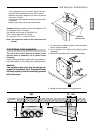
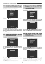
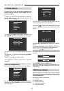
HORIZONTAL
DEFLECTION
VERTICAL
DEFLECTION
RED
GREEN
BLUE
R
G
B
BLUE WIRE GREEN WIRE
RED WIRE
YELLOW WIRE
CEILING DESKTOP PROJECTION
HORIZONTAL
DEFLECTION
CONNECTORS
VERTICAL
DEFLECTION
CONNECTORS
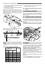
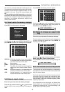
RED
GREEN
BLUE
R
G
B
BLUE WIRE YELLOW WIRE
RED WIRE
GREEN WIRE
REAR DESKTOP PROJECTION
HORIZONTAL
DEFLECTION
CONNECTORS
VERTICAL
DEFLECTION
CONNECTORS
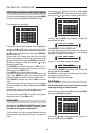
RED
GREEN
BLUE
R
G
B
RED WIRE GREEN WIRE
BLUE WIRE
YELLOW WIRE
REAR CEILING PROJECTION
HORIZONTAL
DEFLECTION
CONNECTORS
VERTICAL
DEFLECTION
CONNECTORS