


C H A P T E R 3
Usingyour interactivewhiteboardsystem
24 smarttech.com/kb/170401
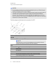
N O TE S
l For more details on the status of your interactive whiteboard system, go to Determining your
interactive whiteboard system’s status on page 46.
l Low Power mode reduces your interactive whiteboard system’s power consumption when it is
in Standby mode.To set the projector system to enter Low Power mode automatically
whenever it enters Standby mode, hold down the Power and Input buttons at the same
time for five seconds. After five seconds, the Power button blinks amber for two seconds to
indicate that Low Power mode is enabled.
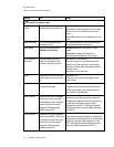
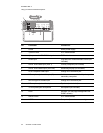
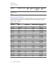
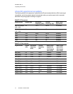
The following diagram and table describe the components of the ECP.
Number Function
Left side
1 USB A receptacle (for USB drives)
N O TE
USB drives that you connect to this receptacle are only accessible to the room
computer (the computer connected to the USB1 receptacle).
Front
2
Power button and status indicator light
3 Volume control
4 Input selection
Back
5 Two mini USB B receptacles (connect to room computer and laptop)
6 11-pin connector (connects to ECP cable harness)
7 4-pin connector (for optional room control)